- Catalogs
- TOPWAY LCD
- Sitronix ST7529 LCD Controller/Driver
- Company
- Products
- Catalogs
- News & Trends
- Exhibitions
Sitronix ST7529 LCD Controller/Driver
1 /86Pages

Sitronix ST7529 LCD Controller/Driver
1 /86Pages
Catalog excerpts

32 Gray Scale Dot Matrix LCD Controller/Driver 1. INTRODUCTION The ST7529 is a driver & controller LSI for 32 gray scale graphic dot-matrix liquid crystal display systems. It generates 255 Segment and 160 Common driver circuits. This chip is connected directly to a microprocessor, accepts Serial Peripheral Interface (SPI), 8-bit/16-bit parallel or IIC display data and stores in an on-chip display data RAM. It performs display data RAM read/write operation with no external operating clock to minimize power consumption. In addition, because it contains power supply circuits necessary to drive liquid crystal, it is possible to make a display system with the fewest components. 2. FEATURES Driver Output Circuits On-chip Low Power Analog Circuit −255 segment outputs / 160 common outputs − On-chip oscillator circuit Applicable Duty Ratios − Various partial display − Partial window moving & data scrolling Microprocessor Interface Operating Voltage Range − 8/16-bit parallel bi-directional interface with 6800-series −4-line serial interface (write only) − LCD driving voltage (VLCD = V0 - VSS): 3.76 to 18.0V −9 bit 3-line serial interface (write only) Temperature Gradient Coefficient On-chip Display Data RAM LCD driving voltage (EEPROM) − To store contrast adjustment value for better display Package Type − Application for COG and TCP
Open the catalog to page 1
ST7529 3. Pad Arrangement Chip Size : 16.550mm x 1.525mm Pad pitch : Com, Seg pad pitch: 43µm IO pad pitch: 110µm Test pin pad pitch: 75µm Pad size : Com, Seg pad size: Pad No1~362 : 25µm (X) x 96µm (Y) Pad No363~390 : 96µm (X) x 25µm (Y) Pad No544~571 : 96µm (X) x 25µm (Y) IO pad pad size: 90µm (X) x 40µm (Y) Test pin pad size: 55µm (X) x 40µm (Y) Bump Height: 17µm Chip Thickness: 635µm
Open the catalog to page 2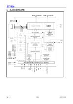
SEGMENT DRIVERS COMMON DRIVERS DATA LATCHES COMMON OUTPUT CONTROLLER CIRCUIT V/F Circuit FRC/PWM FUNCTION CIRCUIT DISPLAY ADDRESS COUNTER ADDRESS COUNTER DATA REGISTER INSTRUCTION REGISTER VLCDin VLCDout INSTRUCTION DECODER TIMING GENERATOR DISPLAY DATA RAM (DDRAM) [160X255X5]
Open the catalog to page 11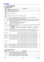
I/O Supply Power supply for logic circuit Supply Power supply for OSC circuit Supply Power supply for Booster Circuit Supply Power supply for LCD Supply Ground. Ground system should be connected together. If the internal voltage generator is used, the VLCDIN & VLCDOUT must be connected together. If an external supply is used, this pin must be left open. An external LCD supply voltage can be supplied using the VLCDIN pad. In this case, VLCDOUT has to be Supply left open, and the internal voltage generator has to be programmed to zero. (SET register VB=0) LCD driver supply voltages V0In & V0out...
Open the catalog to page 12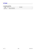
ST7529 6.3 SYSTEM CONTROL Name TCAP T[0]~T[10] Description Test pin. Leave it open. Test pin. Leave it open.
Open the catalog to page 13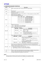
ST7529 6.4 MICROPROCESSOR INTERFACE Name Reset input pin When RST is “L”, initialization is executed. Chip select input pins Data/instruction I/O is enabled only when XCS is "L". When chip select is non-active, DB0 to DB15 may be high impedance. Parallel / Serial data input select input IF1 IF2 IF3 MPU interface type H H H L L L Description M0,M1 must be fixed to VSS. This pin is reserved for internal setting. Read / Write control input pin RW = “H” : read RW = “L” : write Write enable clock input pin The data on DB0 to DB15 are latched at the rising edge of the /WR signal. Read / Write execution...
Open the catalog to page 14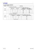
ST7529 6.5 LCD DRIVER OUTPUTS Name Description LCD segment driver outputs The display data and the M signal control the output voltage of segment driver. Segment driver output voltage Display data M (Internal) Normal display Reverse display H H L L Power save mode LCD common driver outputs The internal scanning data and M signal control the output voltage of common driver. Scan data M (Internal) Common driver output voltage O H L H L Power save mode
Open the catalog to page 15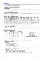
ST7529 7. FUNCTIONAL DESCRIPTION 7.1 MICROPROCESSOR INTERFACE Chip Select Input The XCS pin is for chip selection. The ST7529 can function with an MPU when XCS is "L". In case of serial interface, the internal shift register and the counter are reset. 7.1.1 Selecting Parallel / Serial Interface ST7529 has seven types of interface with an MPU, which are four parallel and three serial interfaces. This parallel or serial interface is determined by IF pin as shown in table 7.1.1. Table 7.1.1 Parallel / Serial Interface Mode IF1 IF2 IF3 Interface type H H H 80 serial 16-bit parallel H H L 80 serial...
Open the catalog to page 16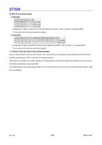
A single pixel of data is read after the second write operation as shown, and it is written in the display RAM. “X” are dummy bits, which are ignored for display. 7.1.3 8-bit (4 line) and 9-bit (3 line) Serial Interface The 8-bit serial interface uses four pins XCS, SI, SCL, and A0 to enter commands and data. Meanwhile, the 9-bit serial interface uses three pins XCS, SI and SCL for the same purpose. Data read is not available in the serial interface. The entered data must be 8 bits. Refer to the following chart for entering commands, parameters or gray-scale data. The relation between gray-scale...
Open the catalog to page 17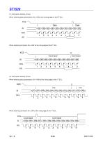
ST7529 (1) 8-bit serial interface (4 line) th When entering data (parameters): A0= HIGH at the rising edge of the 8 SCL. When entering command: A0= LOW at the rising edge of the 8 SCL (2) 9-bit serial interface (3 line) st When entering data (parameters): SI= HIGH at the rising edge of the 1 SCL. When entering command: SI= LOW at the rising edge of the 1 SCL.
Open the catalog to page 18
ST7529 If XCS is set to HIGH while the 8 bits from D7 to D0 are entered, the data concerned is invalid. Before entering succeeding sets of data, you must correctly input the data concerned again. In order to avoid data transfer error due to incoming noise, it is recommended to set XCS at HIGH on byte basis to initialize the serial-to-parallel conversion counter and the register. th When executing the command RAMWR, set XCS to HIGH after writing the last address (after starting the 9 pulse in th case of 9-bit serial input or after starting the 8 pulse in case of 8-bit serial input).
Open the catalog to page 19All TOPWAY LCD catalogs and technical brochures
 TOPWAY Smart LCD SGTools Handbook
108 Pages
 10.1" TFT LCD Module
1 Page
 MONO Product
2 Pages
 LMT050DNCFWU-NNA-2
15 Pages
 LMT080TDGP01
16 Pages
 HKT035BTB-1D
36 Pages
 HMT050AMC-C
17 Pages
 HMT043ATA-6C
31 Pages
 TM035PDHG09
42 Pages
 TM035PDHG03
31 Pages
 TM028HDZP01
28 Pages
 LM256160DCW-1
14 Pages
 LM12896FCW-1
17 Pages
 LM12832KCW
13 Pages
 LM2088EFW-9
12 Pages
 LM3122AGG-2
12 Pages
 LM240160YCW
18 Pages
 LM6093ACW
14 Pages
 HMT104ATA-C
11 Pages
 HMT101ATA-D
36 Pages
 HKT080ATA-C
1 Page
 HMT080ATA
1 Page
 HKT070DTA-1C
11 Pages
 HMT070DTA-D
1 Page
 HKT070DMC-2C
19 Pages
 HMT070ETD-C
31 Pages
 HMT070ETD-1D
34 Pages
 HMT056ATA-C
1 Page
 HMT050CB-1C
31 Pages
 HMT050DTA-D
1 Page
 HKT050ATA-C
1 Page
 HMT043ATA-7C
32 Pages
 HMT043GTA-1D
37 Pages
 HKT043BMC-2C
17 Pages
 HMT043ATA-3C
11 Pages
 HMT043BMC-C
1 Page
 HMT043ATA-4C
11 Pages
 HKT043BMC-C
1 Page
 HKT043ATA-1C
12 Pages
 HMT035ATA-D
13 Pages
 HMT028ATB-C
12 Pages
 HKT104ATA-C
31 Pages
 HMT068BTA-C
33 Pages
 HMT070ATA-1C
32 Pages
 HMT080ATA-C
33 Pages
 HMT090ATA-C
30 Pages
 HMT101ATA-C
33 Pages
 HMT050ATA-2C
31 Pages
 HMT043ATA-2C
32 Pages
 IC Raio RA6963 LCD Controller
42 Pages
 IC Epson S1D13L01 LCD Controller
118 Pages
 IC EPSON S1D13700 LCD Controller
133 Pages
 EPSON S1D13709 LCD Controller
192 Pages
 Samsung S6B0108 LCD Driver
23 Pages
 Avant SBN0064G LCD Driver
37 Pages
 Avant SBN6400G LCD Driver
34 Pages
 EPSON SED1335 LCD Controller
95 Pages
 SGS-THOMSON ST7282
23 Pages
 Raio RA6963 LCD Controller
42 Pages
 Raio RA8875 TFT LCD Controller
174 Pages
 Raio RA8835 LCD Controller
93 Pages
 RAIO RA8803 LCD Controller
8 Pages
 HMT035ATA-1C
1 Page
 Smart LCD introduction
14 Pages
 Topway company introduction
14 Pages
 TFT module in bezel
1 Page
 Topway TFT LCD
1 Page
 LM12864L Series
1 Page
 LM12864T Series
1 Page
 LM12864F Series
1 Page
 LM6060C Series
1 Page
 LM12864M Series
1 Page
 LM6029A Series
1 Page
 LM6059B Series
1 Page
 LM24048A Series
1 Page
 LM13232A Series
1 Page
 LM160160A Series
1 Page
 LMB402C Series
1 Page
 LMB242A Series
1 Page
 LMB204C Series
1 Page
 LM3121 Series
1 Page
 LMB404A Series
1 Page
 HMT043FC-1C
1 Page
 LM3123 Series
1 Page
 LMB204B Series
1 Page
 LMB202E Series
1 Page
 LMB202D Series
1 Page
 LMB164A Series
1 Page
 LMB162G Series
1 Page
 LMB162H Series
1 Page
 LMB162N Series
1 Page
 LMB162A Series
1 Page
 LMB0820D Series
1 Page
 LMB0820C Series
1 Page
 LMB0820A Series
1 Page
 LMB081N Series
1 Page
 LMB081A Series
1 Page
 LMB162X series
1 Page
 LMT057DNAFWU-AAN series
1 Page
 LMT057DNAFWU-AAA series
1 Page
 LMT104SDH01 Series
1 Page
 TOPWAY Product List (Y2012)
4 Pages
 TFT LCD module
1 Page
 Without controller
1 Page
 Chinese fonts
1 Page
 Built-in controller
1 Page
 Character module
1 Page


- Bourn And Koch touch screen monitor
- Bourn And Koch industrial monitor
- Bourn And Koch LCD display
- Bourn And Koch HDMI monitor
- Bourn And Koch VESA mounting monitor
- Bourn And Koch industrial display
- Bourn And Koch TFT LCD display
- Bourn And Koch IP65 monitor
- Bourn And Koch touch screen display
- Bourn And Koch color display
- LED display panel
- Bourn And Koch high-brightness monitor
- Bourn And Koch TFT monitor
- Bourn And Koch electronic display
- Control display system
- Bourn And Koch wall-mount monitor
- IPS display panel
- Bourn And Koch backlit display
- Programmable display system