- Catalogs
- TOPWAY LCD
- SGS-THOMSON ST7282
- Company
- Products
- Catalogs
- News & Trends
- Exhibitions
SGS-THOMSON ST7282
1 /23Pages

SGS-THOMSON ST7282
1 /23Pages
Catalog excerpts
ST7282A5 - ST7282B5 ROM FROM EPROM PRELIMINARY DATASHEET s s 24 digital I/O (ST7 IO3) with pull up, interrupt input, analog input, push-pull/ open drain output 36 LCD/IO combi pins (ST7 LCIO1) with pull-up, interrupt input, push-pull, open drain output, LCD output Group & Block Sync Module for RDS (ST7 RDS GB)
Open the catalog to page 1
Figure 1. Block Diagram
Open the catalog to page 2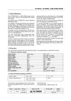
1.1 Quick Reference The ST7282A5/B5 is a 32K ROM version of the ST72 family, using the ST72CORE and N-Well technology. It is derived from EPROM M4 version replacing EPROM by ROM. Two different commercial products are supported by this device : ST7282A5 (no LCD driver) functionnality described in specification SD70KL1618 ed. F) and ST7282B5 (LCD driver) functionnality described in specification 96096 ed. B). It contains an LCD controller/driver with 20 segment and 16 backplane outputs able to drive up to 20 x 16 = 320 segments. The LCD control logic reads automatically data from the LCD-RAM independently...
Open the catalog to page 3
1.2.3 Electrical Characteristics The values given in the specifications of dedicated functions are generally not applicable for chips. Therefore, only the limits listed below are valid for the product. T = -40 ... +85°C, VDD - VSS = 5V unless otherwise specified. PARAMETER Supply voltage Supply current Run Mode Supply current Wait Mode Supply current slow wait mode Supply current halt mode Supply current Reset Mode f=8.55MHz Display voltage Supply voltage differences (VDD, VDDP, VDDA) (VSS, VSSP, VSSA) OSCILLATOR: Input/output cap Cin, Cout Oscillation frequency Built up time 2) Input current...
Open the catalog to page 4
I/O PORTS: Input leakage current 7) Input leakage current Input voltage high leading edge trailing edge Output voltage high Output voltage high Output voltage slope Output current slope Noise amplitude Pullup Resistor Current Total Error tcon Conversion time Analog source impedance Osc. frequency range LCD DRIVER: Frame frequency COM output voltage high SEG output voltage high EEPROM: Write time 1)Operation below 30 KHz Mis possible but requires increased supply current 2)Time to build up the oscillation amplitude to 90% VDD 3)Pull-up resistor 4)WD not active 5)WD generating a reset 6)Period...
Open the catalog to page 5
8) noise at VDD, VSS < 10 mV 9)The DC offset voltage refers to all segment and common outputs. It is the difference between the measured voltage value and nominal voltage value for every voltage level. Rin of voltage meter must be > 10 MΩ.
Open the catalog to page 6
1.3 ST7282A5/B5 ADDRESS MAPPING ADDR. Port A Data Direction Reg. Port B Data Direction Reg. Port C Data Direction Reg. Port D Data Direction Reg.
Open the catalog to page 7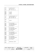
Port E Data Register Port E Data Direction Register Port E Option Register Port F Data Register Port F Data Direction Register Port F Option Register Port G Data Register Port G Data Direction Register Port G Option Register Port H Data Register Port H Data Direction Register Port H Option Register
Open the catalog to page 9
EEPROM read out protected not available (test area) reserved (ST Routram area) user vectors “Not to be used” is mandatory. Any access would modify the functionality.
Open the catalog to page 10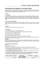
2 IMPLEMENTATION REMARKS OF THE DEDICATIONS In this chapter the options of the dedications, which are implemented are described. The dedications are described in detail in the target specs of the dedications. In case of discrepancies between this specification and the specs. of the dedications, this specification is valid. 2.1 Core 2.1.1 Oscillator The oscillator can be used with quartz or ceramic resonator. The pins OSCIN and OSCOUT permit connection to the on chip clock oscillator circuit. OSCIN is the input, OSCOUT the clock oscillator output. A quartz or a ceramic resonator can be connected...
Open the catalog to page 11
Figure 2. External Interrupt Options INTP I1 External Interrupt Options Negative edge and Low level sensitive Negative edge only Positive edge only Positive and negative edge sensitive 2.2 LCD controller/driver The LCD module contains an LCD controller/driver with 20 segment and 16 backplane outputs able to drive up to 20 x 16 = 320 segments. The LCD control logic reads automatically data from the LCD-RAM independently from the ST72 core. Two signals (LCF32K,LCSYNCHINOUT) can be activated on pins PC0, PC1 to connect a slave display chip for expanding the number of segments. To activate these...
Open the catalog to page 12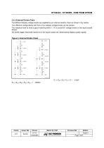
2.2.2 External Divider Chain The different display voltage levels are supplied by an external resistor chain as shown in fig. below. Two different configurations with five or four display voltage levels can be chosen. The resistors have to have a good matching within < 1% to avoid DC voltage levels on the liquid crystal device. DC levels trigger electrode reactions on the liquid crystal cell, deteriorating display quality rapidly. Figure 3. External Divider Chain VLCD VLCD
Open the catalog to page 13
2.2.2.1 Working with 1/5 Bias Figure 4. Waveform on common and on segment output working with 1/5 Bias VLCD BACKP LANE SELECTED
Open the catalog to page 14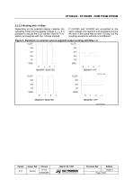
2.2.2.2 Working with 1/4 Bias Depending on the selected display material, the operating mode and the display voltage VLCD, it is possible to reduce the LCD resistor chain to 4 resistors, and operate with the 1/4 bias method. If VLCD35 and VLCD25 are connected to the same voltage, the segment and backplane drivers will work in the same way as with 1/5 bias, but the resulting waveforms will look a bit different : Figure 5. Waveform on common and on segment output working with Bias 1/4 VLCD SEGMENT SELECTED SEGMENT SELECTED
Open the catalog to page 15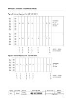
Figure 6. Address Mapping of the LCD-RAM MUX16 Figure 7. Address Mapping of the LCD-RAM MUX8 BP1
Open the catalog to page 16
Figure 8. Address Mapping of the LCD-RAM MUX4 2.3 TIMER 4 16 bit autoreload timer with 2 capture inputs connected to PA0, PA1 (see spec. ST7TIM4). The in- put clock of the timer is fosc divided by 2. 2.4 WATCHDOG The WD2 is used to reset the ST7282 B5 after a certain period of time in the range of 2.8 msec up to 184 msec when fOSC = 8.55 MHz is used. WD2 will be activated, if bit0 in Watchdog Reg. (Adr. 12h) is set ("1"). Once WD2 is running, any software access to bit0 in Watchdog Reg. will NOT influence WD2. However, a RESET signal (either externally or caused by WD2) will reset bit0 of Watchdog...
Open the catalog to page 17All TOPWAY LCD catalogs and technical brochures
 TOPWAY Smart LCD SGTools Handbook
108 Pages
 10.1" TFT LCD Module
1 Page
 MONO Product
2 Pages
 LMT050DNCFWU-NNA-2
15 Pages
 LMT080TDGP01
16 Pages
 HKT035BTB-1D
36 Pages
 HMT050AMC-C
17 Pages
 HMT043ATA-6C
31 Pages
 TM035PDHG09
42 Pages
 TM035PDHG03
31 Pages
 TM028HDZP01
28 Pages
 LM256160DCW-1
14 Pages
 LM12896FCW-1
17 Pages
 LM12832KCW
13 Pages
 LM2088EFW-9
12 Pages
 LM3122AGG-2
12 Pages
 LM240160YCW
18 Pages
 LM6093ACW
14 Pages
 HMT104ATA-C
11 Pages
 HMT101ATA-D
36 Pages
 HKT080ATA-C
1 Page
 HMT080ATA
1 Page
 HKT070DTA-1C
11 Pages
 HMT070DTA-D
1 Page
 HKT070DMC-2C
19 Pages
 HMT070ETD-C
31 Pages
 HMT070ETD-1D
34 Pages
 HMT056ATA-C
1 Page
 HMT050CB-1C
31 Pages
 HMT050DTA-D
1 Page
 HKT050ATA-C
1 Page
 HMT043ATA-7C
32 Pages
 HMT043GTA-1D
37 Pages
 HKT043BMC-2C
17 Pages
 HMT043ATA-3C
11 Pages
 HMT043BMC-C
1 Page
 HMT043ATA-4C
11 Pages
 HKT043BMC-C
1 Page
 HKT043ATA-1C
12 Pages
 HMT035ATA-D
13 Pages
 HMT028ATB-C
12 Pages
 HKT104ATA-C
31 Pages
 HMT068BTA-C
33 Pages
 HMT070ATA-1C
32 Pages
 HMT080ATA-C
33 Pages
 HMT090ATA-C
30 Pages
 HMT101ATA-C
33 Pages
 HMT050ATA-2C
31 Pages
 HMT043ATA-2C
32 Pages
 IC Raio RA6963 LCD Controller
42 Pages
 IC Epson S1D13L01 LCD Controller
118 Pages
 IC EPSON S1D13700 LCD Controller
133 Pages
 EPSON S1D13709 LCD Controller
192 Pages
 Samsung S6B0108 LCD Driver
23 Pages
 Avant SBN0064G LCD Driver
37 Pages
 Avant SBN6400G LCD Driver
34 Pages
 EPSON SED1335 LCD Controller
95 Pages
 Raio RA6963 LCD Controller
42 Pages
 Raio RA8875 TFT LCD Controller
174 Pages
 Raio RA8835 LCD Controller
93 Pages
 RAIO RA8803 LCD Controller
8 Pages
 HMT035ATA-1C
1 Page
 Smart LCD introduction
14 Pages
 Topway company introduction
14 Pages
 TFT module in bezel
1 Page
 Topway TFT LCD
1 Page
 LM12864L Series
1 Page
 LM12864T Series
1 Page
 LM12864F Series
1 Page
 LM6060C Series
1 Page
 LM12864M Series
1 Page
 LM6029A Series
1 Page
 LM6059B Series
1 Page
 LM24048A Series
1 Page
 LM13232A Series
1 Page
 LM160160A Series
1 Page
 LMB402C Series
1 Page
 LMB242A Series
1 Page
 LMB204C Series
1 Page
 LM3121 Series
1 Page
 LMB404A Series
1 Page
 HMT043FC-1C
1 Page
 LM3123 Series
1 Page
 LMB204B Series
1 Page
 LMB202E Series
1 Page
 LMB202D Series
1 Page
 LMB164A Series
1 Page
 LMB162G Series
1 Page
 LMB162H Series
1 Page
 LMB162N Series
1 Page
 LMB162A Series
1 Page
 LMB0820D Series
1 Page
 LMB0820C Series
1 Page
 LMB0820A Series
1 Page
 LMB081N Series
1 Page
 LMB081A Series
1 Page
 LMB162X series
1 Page
 LMT057DNAFWU-AAN series
1 Page
 LMT057DNAFWU-AAA series
1 Page
 LMT104SDH01 Series
1 Page
 TOPWAY Product List (Y2012)
4 Pages
 TFT LCD module
1 Page
 Without controller
1 Page
 Chinese fonts
1 Page
 Built-in controller
1 Page
 Character module
1 Page


- Bourn And Koch touch screen monitor
- Bourn And Koch industrial monitor
- Bourn And Koch LCD display
- Bourn And Koch HDMI monitor
- Bourn And Koch VESA mounting monitor
- Bourn And Koch industrial display
- Bourn And Koch TFT LCD display
- Bourn And Koch IP65 monitor
- Bourn And Koch touch screen display
- Bourn And Koch color display
- LED display panel
- Bourn And Koch high-brightness monitor
- Bourn And Koch TFT monitor
- Bourn And Koch electronic display
- Control display system
- Bourn And Koch wall-mount monitor
- IPS display panel
- Bourn And Koch backlit display
- Programmable display system