- Catalogs
- TOPWAY LCD
- Raio RA8835 LCD Controller
- Company
- Products
- Catalogs
- News & Trends
- Exhibitions
Raio RA8835 LCD Controller
1 /93Pages

Raio RA8835 LCD Controller
1 /93Pages
Catalog excerpts
RAiO RA8835 Dot Matrix LCD Controller Specification Version 2.0 February 12, 2007 RAiO Technology Inc. ©Copyright RAiO Technology Inc. 2005, 2006, 2007
Open the catalog to page 1
Update History Version Update Package Information: Figure 4-1, 4-2, Chapter 9-3, 9-4. Update the index of Figure and Table Add Appendix A: System Suggestion Formal Release 1. Update Figure 7-6: C/R to TC/R Time Difference. 2. Update Figure 7-9. 1.6 3. Update the Notes of Figure7-16 4. Update the Unit of “Input leakage current”, “Output leakage current” and Quiescent supply current of page76 and page 77. 5. Update Note 6 page 78. Update Section 9-4 RA8835P4N Package Dimension 1.7 Update Section 10-2 DC Characteristic Update Parameters of Section 10-3-1, 10-3-2, 10-3-6, 10-3-7 Add Appendix B :...
Open the catalog to page 2
1. Overview The RA8835 is a controller IC that can display text and graphics on LCD panel. It can display layered text and graphics, scroll the display in any direction and partition the display into multiple screens. It also stores text, character codes and bitmapped graphics data in external frame buffer memory. Display controller functions include transferring data from the controlling microprocessor to the buffer memory, reading memory data, converting data to display pixels and generating timing signals for the buffer memory, LCD panel. The RA8835 has an internal character generator with...
Open the catalog to page 6
VD4 VD5 VD6 VD7 YSCL YD YDIS WF LP GND XSCL SECL XD0 XD1 XD2 5. Pin Descriptions 5-1 Pin Functions 5-1-1 MCU Interface Pin Name D0 to D7 Function MCU Data Bus. Tristate input/output pins. Connect these pins to an 8- or 16-bit microprocessor bus. MCU Interface Select. The RA8835 series supports both 8080 family processors (such as the 8085 and Z80®) and 6800 family processors (such as the 6802 and 6809). SEL1 SEL1 should be tied directly to VDD or VSS to prevent noise. If noise does appear on SEL1, decouple it to ground using a capacitor placed as close to the pin as possible. Read Control or...
Open the catalog to page 7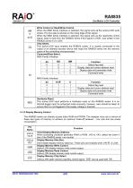
Write Control or Read/Write Control. When the 8080 family interface is selected, this signal acts as the active-LOW write strobe. The bus data is latched on the rising edge of this signal. When the 6800 family interface is selected, this signal acts as the read/write control signal. Data is read from the RA8835 series if this signal is HIGH, and written to the RA8835 series if it is LOW. Chip Select. This active-LOW input enables the RA8835 series. It is usually connected to the output of an address decoder device that maps the RA8835 series into the memory space of the controlling microprocessor....
Open the catalog to page 8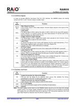
5-1-3 LCD Drive Signals In order to provide effective low-power drive for LCD matrixes, the RA8835 series can directly control both the X- and Y-drivers using an enable chain. Function Data Output for Driver. 4-bit X-driver (column drive) data outputs. Connect these outputs to the inputs of the X-driver chips. Latch Clock. The falling edge of XSCL latches the data on XD0 to XD3 into the input shift registers of the X-drivers. To conserve power, this clock halts between LP and the start of the following display line (See section 6-3-7). Trigger Clock for Chain Cascade. The falling edge of XECL...
Open the catalog to page 9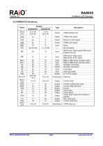
VRAM write signal Memory control signal VRAM read signal 8080 family: Read signal 6800 family: Enable clock (E) 8080 family: Write signal 6800 family: R/ W signal Input Input Input Output Input Input Supply X-driver data Output Output Supply Output Output Output Output X-driver enable chain clock X-driver data shift clock Ground Latch pulse Frame signal Power-down signal when display is blanked Scan start pulse Y-driver shift clock 8080 or 6800 family interface select 8080 or 6800 family interface select Oscillator connection Oscillator connection Chip select Data type select 2.7 to 5.5V supply...
Open the catalog to page 10
6. Instruction Set 6-1 The Command Set Table-1: Command Set Command Code Class Command Description DISPLAY ON/OFF Initialize device and display Enter standby mode Read Parameters No. of Section Bytes 8 Enable and disable display and display flashing Set display start address and display regions CSRFORM Display Set start address of character generator Set direction of cursor movement Set horizontal scroll position Read cursor address Memory Control Set display overlay format Write to display memory Read from display memory Notes: 1. In general, the internal registers of the RA8835 series are modified...
Open the catalog to page 11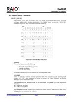
6-2 System Control Commands 6-2-1 SYSTEM SET Initializes the device, sets the window sizes, and selects the LCD interface format. Since this command sets the basic operating parameters of the RA8835 series, an incorrect SYSTEM SET command may cause other commands to operate incorrectly. MSB Figure 6-1: SYSTEM SET Instruction 6-2-1-1 C This control byte performs the following: 1. Resets the internal timing generator 2. Disables the display 3. Cancels sleep mode Parameters following P1 are not needed if only canceling sleep mode. 6-2-1-2 M0 Select the internal or external character generator ROM....
Open the catalog to page 12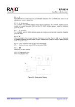
6-2-1-3 M1 Select the memory configuration for user-definable characters. The CG RAM codes select one of the 64 codes shown in figure 7-29. M1 = 0: No D6 correction. The CG RAM1 and CG RAM2 address spaces are not contiguous, the CG RAM1 address space is treated as character generator RAM, and the CG RAM2 address space is treated as character generator ROM. M1 = 1: D6 correction. The CG RAM1 and CG RAM2 address spaces are contiguous and are both treated as character generator RAM. 6-2-1-4 M2 Select the height of the character bitmaps. Characters more than 16 pixels high can be displayed by creating...
Open the catalog to page 13
Upper Panel Lower Panel Figure 6-3: Above and Below Two-panel Display Left Panel Right Panel Figure 6-4: Left-and-Right Two-panel Display Note: There are no RAiO LCD units in the configuration shown in Figure 6-4.
Open the catalog to page 14
L/F 00H to L/F + 1 (See note 2.) 00H to L/F + 1 (See note 2.) First screen block Second screen block Third screen block First screen block Second screen block Third screen block Invalid Continuous movement over whole screen First screen block Second screen block Third screen block First screen block Second screen block Third screen block Fourth screen block Fourth screen block Above-and-below configuration: continuous movement over whole screen Notes: 1. See Table-24 for further details on setting the C/R and TC/R parameters when using 2. The value of SL when IV = 0 is equal to the value of SL...
Open the catalog to page 15All TOPWAY LCD catalogs and technical brochures
 TOPWAY Smart LCD SGTools Handbook
108 Pages
 10.1" TFT LCD Module
1 Page
 MONO Product
2 Pages
 LMT050DNCFWU-NNA-2
15 Pages
 LMT080TDGP01
16 Pages
 HKT035BTB-1D
36 Pages
 HMT050AMC-C
17 Pages
 HMT043ATA-6C
31 Pages
 TM035PDHG09
42 Pages
 TM035PDHG03
31 Pages
 TM028HDZP01
28 Pages
 LM256160DCW-1
14 Pages
 LM12896FCW-1
17 Pages
 LM12832KCW
13 Pages
 LM2088EFW-9
12 Pages
 LM3122AGG-2
12 Pages
 LM240160YCW
18 Pages
 LM6093ACW
14 Pages
 HMT104ATA-C
11 Pages
 HMT101ATA-D
36 Pages
 HKT080ATA-C
1 Page
 HMT080ATA
1 Page
 HKT070DTA-1C
11 Pages
 HMT070DTA-D
1 Page
 HKT070DMC-2C
19 Pages
 HMT070ETD-C
31 Pages
 HMT070ETD-1D
34 Pages
 HMT056ATA-C
1 Page
 HMT050CB-1C
31 Pages
 HMT050DTA-D
1 Page
 HKT050ATA-C
1 Page
 HMT043ATA-7C
32 Pages
 HMT043GTA-1D
37 Pages
 HKT043BMC-2C
17 Pages
 HMT043ATA-3C
11 Pages
 HMT043BMC-C
1 Page
 HMT043ATA-4C
11 Pages
 HKT043BMC-C
1 Page
 HKT043ATA-1C
12 Pages
 HMT035ATA-D
13 Pages
 HMT028ATB-C
12 Pages
 HKT104ATA-C
31 Pages
 HMT068BTA-C
33 Pages
 HMT070ATA-1C
32 Pages
 HMT080ATA-C
33 Pages
 HMT090ATA-C
30 Pages
 HMT101ATA-C
33 Pages
 HMT050ATA-2C
31 Pages
 HMT043ATA-2C
32 Pages
 IC Raio RA6963 LCD Controller
42 Pages
 IC Epson S1D13L01 LCD Controller
118 Pages
 IC EPSON S1D13700 LCD Controller
133 Pages
 EPSON S1D13709 LCD Controller
192 Pages
 Samsung S6B0108 LCD Driver
23 Pages
 Avant SBN0064G LCD Driver
37 Pages
 Avant SBN6400G LCD Driver
34 Pages
 EPSON SED1335 LCD Controller
95 Pages
 SGS-THOMSON ST7282
23 Pages
 Raio RA6963 LCD Controller
42 Pages
 Raio RA8875 TFT LCD Controller
174 Pages
 RAIO RA8803 LCD Controller
8 Pages
 HMT035ATA-1C
1 Page
 Smart LCD introduction
14 Pages
 Topway company introduction
14 Pages
 TFT module in bezel
1 Page
 Topway TFT LCD
1 Page
 LM12864L Series
1 Page
 LM12864T Series
1 Page
 LM12864F Series
1 Page
 LM6060C Series
1 Page
 LM12864M Series
1 Page
 LM6029A Series
1 Page
 LM6059B Series
1 Page
 LM24048A Series
1 Page
 LM13232A Series
1 Page
 LM160160A Series
1 Page
 LMB402C Series
1 Page
 LMB242A Series
1 Page
 LMB204C Series
1 Page
 LM3121 Series
1 Page
 LMB404A Series
1 Page
 HMT043FC-1C
1 Page
 LM3123 Series
1 Page
 LMB204B Series
1 Page
 LMB202E Series
1 Page
 LMB202D Series
1 Page
 LMB164A Series
1 Page
 LMB162G Series
1 Page
 LMB162H Series
1 Page
 LMB162N Series
1 Page
 LMB162A Series
1 Page
 LMB0820D Series
1 Page
 LMB0820C Series
1 Page
 LMB0820A Series
1 Page
 LMB081N Series
1 Page
 LMB081A Series
1 Page
 LMB162X series
1 Page
 LMT057DNAFWU-AAN series
1 Page
 LMT057DNAFWU-AAA series
1 Page
 LMT104SDH01 Series
1 Page
 TOPWAY Product List (Y2012)
4 Pages
 TFT LCD module
1 Page
 Without controller
1 Page
 Chinese fonts
1 Page
 Built-in controller
1 Page
 Character module
1 Page


- Monitor with touchscreen
- Industrial monitor
- LCD display panel
- HDMI monitor
- VESA mounting monitor
- Industrial display panel
- TFT display module
- IP65 monitor
- Touch screen display panel
- Color display panel
- LED display panel
- High-brightness monitor
- TFT-LCD monitor
- Electronic display panel
- Control display system
- Wall-mount monitor
- IPS display panel
- Backlit display panel
- Programmable display system