- Catalogs
- TOPWAY LCD
- RAIO RA8803 LCD Controller
- Company
- Products
- Catalogs
- News & Trends
- Exhibitions
RAIO RA8803 LCD Controller
1 /8Pages

RAIO RA8803 LCD Controller
1 /8Pages
Catalog excerpts
RAiO RA8803/8822 Two Layers Text/Graphic LCD Controller Specification Version 2.1 August 4, 2005 RAiO Technology Inc. ©Copyright RAiO Technology Inc. 2004, 2005
Open the catalog to page 1
Two Layers Character/Graphical LCD Controller 1. General Description The RA8803/RA8822 is a Dot-Matrix LCD controller which support both text and graphics mode. It built-in two Display RAM for two layers display, and an embedded 512Kbyte character ROM that consists of Chinese, English and ASCII fonts. In text mode, the RA8803/8822 support Chinese BIG5 code or GB code. The system (MPU) does not need take a lot of time to show the Chinese font in graphics mode. The RA8803/8822 support 8080/6800 like MPU interface, and also provide 4-Bit or 8-Bit data bus. For LCD driver interface, it support the...
Open the catalog to page 2
Two Layers Character/Graphical LCD Controller 3. Block Diagram Figure 3-1 is the internal block diagram of RA8803. The RA8803 consists of Display RAM, 512Kbyte Font ROM, Command Registers, Analog to Digital Converter(ADC), Digital to Analog Converter(DAC), Display Timing Generator(DTG) and Microprocessor interface. Figure 3-2 is the internal block diagram of RA8822. The major different of RA8803 and RA8822 is the Display RAM size. The RA8803 built-in two 9.6Kbyte display RAM, and RA8822 built-in two 4.8Kbyte. DISPLAY DATA SRAM (9.6KByte x 2) REGISTER CIRCUIT DISPLAY TIMING GENERATOR CIRCUIT SYSTEM...
Open the catalog to page 3
Two Layers Character/Graphical LCD Controller DISPLAY DATA SRAM (4.8KByte x 2) DISPLAY TIMING GENERATOR CIRCUIT REGISTER CIRCUIT SYSTEM CONFIGURE CIRCUIT Figure 3-2: RA8822 Block Diagram 4. Pin Definition 4.1 MPU Interface Pin Name These are data bus for data transfer between MPU and RA8803/8822. The high nibble DB[7..4] should be floating when 4-bit data bus mode is used. Enable/Read Enable When MPU I/F is 8080 series, this pin (RD#) is used as data read, active low. When MPU I/F is 6800 series, this pin (EN) is used as Enable, active high. Write/Read-Write When MPU I/F is 8080 series, this...
Open the catalog to page 4
Two Layers Character/Graphical LCD Controller control. Active high for read and active low for write. Register/Memory Select RS The MPU will access Register when RS is Low and access Data Memory when RS is High. Usually connect to MPU address bus A0. Chip Select The RA8803/8822 is active when CS1# is low and CS2 is high Interrupt Signal This is an interrupt output to indicate the status of RA8803/88822. It could be setup active high or low. Busy Signal This is a busy output to indicate the RA8803/88822 is in busy state. It could be setup active high or low. If setup active high, the RA8803/8822...
Open the catalog to page 5
Two Layers Character/Graphical LCD Controller X’tal Input XA In internal clock mode, this pin connects to external X’tal(32768Hz). In external clock mode, this is an input of external clock. X’tal Output This pin connects to external X’tal(32768Hz). 4.4 Peripheral Interface Pin Name Description Reset Signal This is a reset signal used to reset RA8803/8822. Active low. Touch Panel Input This is connecting to the left pin of 4-wire touch panel. Touch Panel Input This is connecting to the right pin of 4-wire touch panel. Touch Panel Input This is connecting to the top pin of 4-wire touch panel....
Open the catalog to page 6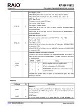
Two Layers Character/Graphical LCD Controller Pull High(1) : 8-Bit When SYS_DW is Pull Low, then the LCD driver data bus Is 4-Bit. When SYS_DW is Pull High, then the LCD driver data bus is 8-Bit. MPU Type Select This pin is used to select MPU type: Pull Low(0) : I8080 Series Pull High(1) : M6800 Series When SYS_MI is Pull Low, then the MPU Interface of RA8803/8822 is suppported I8080. When SYS_MI is Pull High, then the MPU Interface of RA8803/8822 is supported M6800. 8080 MPU Data Bus Select This pin is used to select data bus of 8080 MPU is 4-Bitor 8-Bit: Pull Low(0) : 4-Bit Pull High(1) : 8-Bit...
Open the catalog to page 7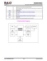
Two Layers Character/Graphical LCD Controller power for internal cells and external device. If the system uses 3.3V power only, then connect this pin to external 3.3V power directly. VDDP Analog Power of ADC for Touch Panel Controller Analog Ground of ADC for Touch Panel Controller Test Pin This pin is for test only and don’t need to connect. 5. System Block Diagram Touch Panel
Open the catalog to page 8All TOPWAY LCD catalogs and technical brochures
 TOPWAY Smart LCD SGTools Handbook
108 Pages
 10.1" TFT LCD Module
1 Page
 MONO Product
2 Pages
 LMT050DNCFWU-NNA-2
15 Pages
 LMT080TDGP01
16 Pages
 HKT035BTB-1D
36 Pages
 HMT050AMC-C
17 Pages
 HMT043ATA-6C
31 Pages
 TM035PDHG09
42 Pages
 TM035PDHG03
31 Pages
 TM028HDZP01
28 Pages
 LM256160DCW-1
14 Pages
 LM12896FCW-1
17 Pages
 LM12832KCW
13 Pages
 LM2088EFW-9
12 Pages
 LM3122AGG-2
12 Pages
 LM240160YCW
18 Pages
 LM6093ACW
14 Pages
 HMT104ATA-C
11 Pages
 HMT101ATA-D
36 Pages
 HKT080ATA-C
1 Page
 HMT080ATA
1 Page
 HKT070DTA-1C
11 Pages
 HMT070DTA-D
1 Page
 HKT070DMC-2C
19 Pages
 HMT070ETD-C
31 Pages
 HMT070ETD-1D
34 Pages
 HMT056ATA-C
1 Page
 HMT050CB-1C
31 Pages
 HMT050DTA-D
1 Page
 HKT050ATA-C
1 Page
 HMT043ATA-7C
32 Pages
 HMT043GTA-1D
37 Pages
 HKT043BMC-2C
17 Pages
 HMT043ATA-3C
11 Pages
 HMT043BMC-C
1 Page
 HMT043ATA-4C
11 Pages
 HKT043BMC-C
1 Page
 HKT043ATA-1C
12 Pages
 HMT035ATA-D
13 Pages
 HMT028ATB-C
12 Pages
 HKT104ATA-C
31 Pages
 HMT068BTA-C
33 Pages
 HMT070ATA-1C
32 Pages
 HMT080ATA-C
33 Pages
 HMT090ATA-C
30 Pages
 HMT101ATA-C
33 Pages
 HMT050ATA-2C
31 Pages
 HMT043ATA-2C
32 Pages
 IC Raio RA6963 LCD Controller
42 Pages
 IC Epson S1D13L01 LCD Controller
118 Pages
 IC EPSON S1D13700 LCD Controller
133 Pages
 EPSON S1D13709 LCD Controller
192 Pages
 Samsung S6B0108 LCD Driver
23 Pages
 Avant SBN0064G LCD Driver
37 Pages
 Avant SBN6400G LCD Driver
34 Pages
 EPSON SED1335 LCD Controller
95 Pages
 SGS-THOMSON ST7282
23 Pages
 Raio RA6963 LCD Controller
42 Pages
 Raio RA8875 TFT LCD Controller
174 Pages
 Raio RA8835 LCD Controller
93 Pages
 HMT035ATA-1C
1 Page
 Smart LCD introduction
14 Pages
 Topway company introduction
14 Pages
 TFT module in bezel
1 Page
 Topway TFT LCD
1 Page
 LM12864L Series
1 Page
 LM12864T Series
1 Page
 LM12864F Series
1 Page
 LM6060C Series
1 Page
 LM12864M Series
1 Page
 LM6029A Series
1 Page
 LM6059B Series
1 Page
 LM24048A Series
1 Page
 LM13232A Series
1 Page
 LM160160A Series
1 Page
 LMB402C Series
1 Page
 LMB242A Series
1 Page
 LMB204C Series
1 Page
 LM3121 Series
1 Page
 LMB404A Series
1 Page
 HMT043FC-1C
1 Page
 LM3123 Series
1 Page
 LMB204B Series
1 Page
 LMB202E Series
1 Page
 LMB202D Series
1 Page
 LMB164A Series
1 Page
 LMB162G Series
1 Page
 LMB162H Series
1 Page
 LMB162N Series
1 Page
 LMB162A Series
1 Page
 LMB0820D Series
1 Page
 LMB0820C Series
1 Page
 LMB0820A Series
1 Page
 LMB081N Series
1 Page
 LMB081A Series
1 Page
 LMB162X series
1 Page
 LMT057DNAFWU-AAN series
1 Page
 LMT057DNAFWU-AAA series
1 Page
 LMT104SDH01 Series
1 Page
 TOPWAY Product List (Y2012)
4 Pages
 TFT LCD module
1 Page
 Without controller
1 Page
 Chinese fonts
1 Page
 Built-in controller
1 Page
 Character module
1 Page


- Monitor with touchscreen
- Industrial monitor
- LCD display panel
- HDMI monitor
- VESA mounting monitor
- Industrial display panel
- TFT display module
- IP65 monitor
- Touch screen display panel
- Color display panel
- LED display panel
- High-brightness monitor
- TFT-LCD monitor
- Electronic display panel
- Control display system
- Wall-mount monitor
- IPS display panel
- Backlit display panel
- Programmable display system