- Catalogs
- TOPWAY LCD
- Raio RA6963 LCD Controller
- Company
- Products
- Catalogs
- News & Trends
- Exhibitions
Raio RA6963 LCD Controller
1 /42Pages

Raio RA6963 LCD Controller
1 /42Pages
Catalog excerpts

RAiO RA6963 Dot Matrix LCD Controller Specification Version 1.7 May 5, 2011 RAiO Technology Inc. ©Copyright RAiO Technology Inc. 2011
Open the catalog to page 1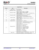
Update History Version Description Formal Release Update Figure 9-4 Update < Table 8-2 > Max. fOSC to 18MHz. Update < Table 8-4 > Max. fSCP to 9MHz. Update the Chapter 5-4 “Misc Interface” – the description of pin “MDS” and MD[1:0]. Update the description of pin “X1” in Section 5-4. Update Figure 6-13, 6-14, 9-5 and 9-6. Update < Table 6-5 > Command Definition Description. Update Figure 6-10. Update < Table 6-31 > Package Description in Section 6-21. Update < Table 8-2 > Update Figure 9-6 Update the Section 7-1 : Die Form Update : delete the description of FONTSEL Update : the description of...
Open the catalog to page 2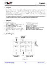
1. Overview The RA6963 is a dot matrix LCD Controller which fully compatible with T6963C. It supports various LCD Driver for standard or custom-made LCD module. The RA6963 built-in a 128-word CG(Character Generator) ROM that for ASCII, Japanese or numeric display in text mode. It also supports Graphics mode and mixed display with Text. The supported maximum external display RAM is 64Kbyte and the display Window can be moved freely within the allocated memory range. The RA6963 has an 8-bit parallel data bus that can be directly connected to an 8080 series MPU. The RA6963 supports a very broad...
Open the catalog to page 5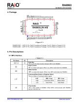
LP CDATA FR CH1 CH2 DSPON VDD SDSEL GND TEST2 TEST1 X1 X2 < Figure 4-1 > RA6963L2NA : LQFP-67 Pin, RoHS Compliance Package, Font-01 (Refer to Chapter 6-16) RA6963L2NB : LQFP-67 Pin, RoHS Compliance Package, Font-02 (Refer to Chapter 6-16) 5. Pin Descriptions 5-1 MPU Interface < Table 5-1 > Pin Name Description Data Bus This is bus for data transfer between MPU and RA6963. Read Control RD is a data read signal. When Low, MPU read data from RA6963. Write Control WR is a data write signal. When Low, MPU write data into RA6963. Command/Data Select or Register Select This is a Data or Command select...
Open the catalog to page 6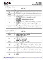
5-2 LCD Driver Interface < Table 5-2 > Pin Name Description Frame Latch Latch pulse for column driver. Shift clock pulse for Row Driver Synchronous Data Synchronous Data for Row Driver. Shift Clock Pulse Shift clock pulse for Column Driver in upper area of LCD. Data Output Data output for Odd Columns in upper area of LCD. Data Output Data output for even columns in both upper and lower SDSEL = Low LCD. Display On DSPON SDSEL = High area of LCD. Data output for columns in both upper and lower area of Display On/Off control signal. When HALT or RST is Low, DSPON output Low (LCD Display Off). 5-3...
Open the catalog to page 7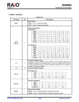
5-4 Misc. Interface < Table 5-4 > Pin Name DUAL Description Scan Select DUAL = Low DUAL = High Dual-Scan Mode. Signal-Scan Mode. LCD Size Selection One Screen DUAL Crystal Oscillator Input A crystal / ceramic oscillator circuit is built in. The oscillation frequency is adjusted according to the display size. If using an external clock, use the X1 pin as the clock input. (X2 open.) External capacitors 15 to 20pF for Crystal or Ceramic oscillator. Crystal Oscillator Output Font Selection Columns Selection Data Transfer Mode Sending data by simple serial mode. Sending data by odd/even separtion...
Open the catalog to page 8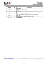
Description Halt Signal HALT = High Reset Signal Normal Mode. Normal mode. RA6963 built-in a Pull-Hi resistor. RST = High Test Pins These are test pins. No need for connection(NC). Check Signals
Open the catalog to page 9
6. Functions Description 6-1 Functional Definition After power on, it is necessary to reset. The RST is kept Low between 5 clocks up (oscillation clock). When HALT = Low, the oscillation stops. The power supply for the LCD must be turned off, to protect the LCD from DC bias. The HALT function( HALT = Low) includes the RESET function( RST =Low). The column/line counter and display register are cleared by RST . (Other registers are not cleared.) Disable the display using the clear-display register The status must be checked before data or commands are sent. The MSB=0 status check must be done in...
Open the catalog to page 10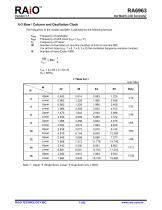
6-3 Row / Column and Oscillation Clock The frequency of the crystal oscillator is adjusted by the following formula. fOSC fSCP fR M N : Frequency of oscillation : Frequency of shift clock (fSCP = fOSC / 2 ) : Frequency of Frame : Number of characters on one line (number of dots on one line 8M) For all font sizes (e.g. 7 x 8, 7 x 8, 5 x 8) the oscillation frequency remains constant. : Number of rows (Duty=1/8N) 8M x 8N= 1 fR fSCP fOSC = fR x 64 x 2 x M x N (fR = 60Hz) < Table 6-2 > Single-Scan. Lower
Open the catalog to page 11
6-4 RAM Interface The external RAM is used to store display data (text, graphic and external CG data). With single-scan, text data, graphic data and external CG data can be freely allocated to the memory area (64 KB max). With dual-scan, LCD-I is allocated to 0000h to 7FFFh (32 KB max), LCD-II is allocated to 8000h to FFFFh (32-KB Max). Text data, graphic data and external CG data can be freely allocated in LCD-I. In LCD-II, the same addresses must be allocated as in LCD-I, except A15. A15 determines selection of LCD-I or LCD-II. It can be used the address-decoded signals CE0 (0000h to 07FFh),...
Open the catalog to page 12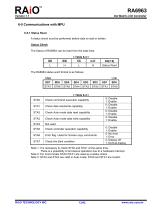
6-5 Communications with MPU 6-5-1 Status Read A status check must be performed before data is read or written. Status Check The Status of RA6963 can be read from the data lines. < Table 6-3 > RD Status Word The RA6963 status word format is as follows: MSB Check command execution capability Check data read/write capability Check Auto mode data read capability Check Auto mode data write capability Check controller operation capability Error flag. Used for Screen copy commands. Check the blink condition 0: Disable 1: Enable 0: Disable 1: Enable 0: Disable 1: Enable 0: Disable 1: Enable 0: Disable...
Open the catalog to page 13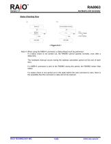
Dot Matrix LCD Controller Status Checking Flow a) AUTO MODE STATUS Note 4: When using the MSB=0 command, a Status Read must be performed. If a status check is not carried out, the RA6963 cannot operate normally, even after a delay time. The hardware interrupt occurs during the address calculation period (at the end of each line). If a MSB=0 command is sent to the RA6963 during this period, the RA6963 enters Wait status. If a status check is not carried out in this state before the next command is sent, there is the possibility that the command or data will not be received.
Open the catalog to page 14All TOPWAY LCD catalogs and technical brochures
 TOPWAY Smart LCD SGTools Handbook
108 Pages
 10.1" TFT LCD Module
1 Page
 MONO Product
2 Pages
 LMT050DNCFWU-NNA-2
15 Pages
 LMT080TDGP01
16 Pages
 HKT035BTB-1D
36 Pages
 HMT050AMC-C
17 Pages
 HMT043ATA-6C
31 Pages
 TM035PDHG09
42 Pages
 TM035PDHG03
31 Pages
 TM028HDZP01
28 Pages
 LM256160DCW-1
14 Pages
 LM12896FCW-1
17 Pages
 LM12832KCW
13 Pages
 LM2088EFW-9
12 Pages
 LM3122AGG-2
12 Pages
 LM240160YCW
18 Pages
 LM6093ACW
14 Pages
 HMT104ATA-C
11 Pages
 HMT101ATA-D
36 Pages
 HKT080ATA-C
1 Page
 HMT080ATA
1 Page
 HKT070DTA-1C
11 Pages
 HMT070DTA-D
1 Page
 HKT070DMC-2C
19 Pages
 HMT070ETD-C
31 Pages
 HMT070ETD-1D
34 Pages
 HMT056ATA-C
1 Page
 HMT050CB-1C
31 Pages
 HMT050DTA-D
1 Page
 HKT050ATA-C
1 Page
 HMT043ATA-7C
32 Pages
 HMT043GTA-1D
37 Pages
 HKT043BMC-2C
17 Pages
 HMT043ATA-3C
11 Pages
 HMT043BMC-C
1 Page
 HMT043ATA-4C
11 Pages
 HKT043BMC-C
1 Page
 HKT043ATA-1C
12 Pages
 HMT035ATA-D
13 Pages
 HMT028ATB-C
12 Pages
 HKT104ATA-C
31 Pages
 HMT068BTA-C
33 Pages
 HMT070ATA-1C
32 Pages
 HMT080ATA-C
33 Pages
 HMT090ATA-C
30 Pages
 HMT101ATA-C
33 Pages
 HMT050ATA-2C
31 Pages
 HMT043ATA-2C
32 Pages
 IC Raio RA6963 LCD Controller
42 Pages
 IC Epson S1D13L01 LCD Controller
118 Pages
 IC EPSON S1D13700 LCD Controller
133 Pages
 EPSON S1D13709 LCD Controller
192 Pages
 Samsung S6B0108 LCD Driver
23 Pages
 Avant SBN0064G LCD Driver
37 Pages
 Avant SBN6400G LCD Driver
34 Pages
 EPSON SED1335 LCD Controller
95 Pages
 SGS-THOMSON ST7282
23 Pages
 Raio RA8875 TFT LCD Controller
174 Pages
 Raio RA8835 LCD Controller
93 Pages
 RAIO RA8803 LCD Controller
8 Pages
 HMT035ATA-1C
1 Page
 Smart LCD introduction
14 Pages
 Topway company introduction
14 Pages
 TFT module in bezel
1 Page
 Topway TFT LCD
1 Page
 LM12864L Series
1 Page
 LM12864T Series
1 Page
 LM12864F Series
1 Page
 LM6060C Series
1 Page
 LM12864M Series
1 Page
 LM6029A Series
1 Page
 LM6059B Series
1 Page
 LM24048A Series
1 Page
 LM13232A Series
1 Page
 LM160160A Series
1 Page
 LMB402C Series
1 Page
 LMB242A Series
1 Page
 LMB204C Series
1 Page
 LM3121 Series
1 Page
 LMB404A Series
1 Page
 HMT043FC-1C
1 Page
 LM3123 Series
1 Page
 LMB204B Series
1 Page
 LMB202E Series
1 Page
 LMB202D Series
1 Page
 LMB164A Series
1 Page
 LMB162G Series
1 Page
 LMB162H Series
1 Page
 LMB162N Series
1 Page
 LMB162A Series
1 Page
 LMB0820D Series
1 Page
 LMB0820C Series
1 Page
 LMB0820A Series
1 Page
 LMB081N Series
1 Page
 LMB081A Series
1 Page
 LMB162X series
1 Page
 LMT057DNAFWU-AAN series
1 Page
 LMT057DNAFWU-AAA series
1 Page
 LMT104SDH01 Series
1 Page
 TOPWAY Product List (Y2012)
4 Pages
 TFT LCD module
1 Page
 Without controller
1 Page
 Chinese fonts
1 Page
 Built-in controller
1 Page
 Character module
1 Page


- Monitor with touchscreen
- Industrial monitor
- HDMI monitor
- VESA mounting monitor
- Industrial display panel
- TFT display module
- IP65 monitor
- Touch screen display panel
- Color display panel
- LED display panel
- High-brightness monitor
- TFT-LCD monitor
- Electronic display panel
- Control display system
- Wall-mount monitor
- IPS display panel
- Backlit display panel
- Programmable display system