
- Catalogs
- TOPWAY LCD
- LMT080TDGP01


- Company
- Products
- Catalogs
- News & Trends
- Exhibitions
LMT080TDGP01

LMT080TDGP01
The LCD module is intended for use in portable DVD players, GPS car TVs, and portable multimedia players, offering a high-quality flat panel display. It replaces outdated CSTN modules in industrial applications and includes a TFT-LCD panel, driver ICs, FPC, and LED backlight unit.
The module features an 8.0” screen with a resolution of 1024(RGB)x768, utilizing a-Si TFT active matrix technology. It measures 183.43x138.35x3.75 mm with an active area of 162.05x121.54 mm. It supports all viewing directions and operates between -20 to +70°C.
The module comprises a signal interface of LVDS 18bit/24bit (VESA), a power circuit, timing circuit, source driver, gate driver, and LED backlight circuit.
The input terminal includes pins for power supply, LVDS differential data input, and control signals. Key pins are VDD for power supply, RESET for global reset, and STBYB for standby mode. It supports 6bit/8bit mode selection and horizontal/vertical scanning direction settings.
The power voltage ranges from -0.3 to 5.0 V for VDD and -0.5 to 13.5 V for AVDD. It operates safely within -20 to +70°C and can be stored between -30 to +80°C. Exceeding these ratings may cause damage.
The module operates at a typical power voltage of 3.3 V for VDD and 12.6 V for AVDD. Current consumption is specified for various components, with a typical forward voltage of 9.3 V for the LED backlight circuit.
Details on LVDS mode DC and AC electrical characteristics, data input format, and optical characteristics, including viewing angles, response time, contrast ratio, and luminance, are provided.
Recommendations include ensuring adjustable V0 and VCOM for optimal contrast, avoiding operation beyond maximum ratings, and minimizing signal line length to reduce noise. The module should be protected from static electricity, mechanical shock, and extreme environmental conditions. Proper handling and storage practices are emphasized to maintain reliability.
- Avoid pressing components on the LCD module to prevent damage.
- Ensure the module is not twisted or deformed during assembly.
- Do not press the LCD screen surface to avoid color abnormalities.
- The screen is made of glass and can be damaged by impacts.
- Be cautious of static electricity when removing the protective film.
- The polarizer is easily scratched; avoid removing the protective film until installation is complete.
- Handle the panel carefully due to sharp edges.
- Do not disassemble or modify the module.
- If liquid crystal leaks, avoid ingestion and wash off any contact immediately.
- Bezel Mounting: Ensure the bezel window is larger than the CTP active area with a gap of ≥0.5mm on each side. Use a gasket between the bezel and CTP surface with a final gap of 0.5~1.0mm. Provide additional support brackets if necessary.
- Surface Mounting: Use double-sided adhesive on a flat, clean countersink area. Maintain a gap of ≥0.3mm around the cover lens. Provide additional support brackets if necessary.
- Additional Cover Lens Mounting: Check CTP specifications for material and thickness. Maintain a 0.2~0.3mm gap between the cover lens and CTP surface. Ensure the cover lens window is larger than the CTP active area with a gap of ≥0.5mm on each side.
- Maintain a gap of 0.2~0.3mm between the bezel and RTP active area to prevent abnormal touch.
- Protect circuit wire areas with a gasket to prevent ITO film deformation and damage.
- Ensure the bezel side wall maintains a space of 0.2~0.3mm from the RTP.
- RTP visible area should be larger than TFT visible area, and RTP active area should be larger than TFT active area.
- The product is guaranteed to perform according to delivery specifications for general electronic products.
- Responsibility is not accepted for use in medical, nuclear, aerospace, fire, and security systems without a separate agreement.
- No responsibility for defects arising from additional manufacturing, strong external force, or static electricity post-inspection.
- CCFL models' performance may vary based on inverter performance; no responsibility for defects or reliability issues.
- No responsibility for third-party intellectual property issues except those related to product structure or manufacturing.
Catalog excerpts

LMT080TDGP01LCD Module User Manual Prepared by:
Open the catalog to page 1
LCD Module User Manual
Open the catalog to page 2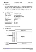
LCD Module User Manual 1. Applications This Module is designed for portable DVD, GPS car TV & PMP(portable multimedia player) application which require high quality flat panel displays. It is also a good substitute for many outmoded CSTN module in the industrial application. This product is composed of a TFT-LCD panel, driver ICs, FPC and LED backlight unit. 2. General Specification Signal Interface : Display Technology : Screen Size(Diagonal) : Outline Dimension : Active Area : Number of dots : Pixel Pitch : Pixel Configuration : Backlight : Surface Treatment : Viewing Direction : Operating...
Open the catalog to page 3
TOPWAY LCD Module User Manual LMT080TDGP01 Note: I/O-—definition, I-—Input, O-—Output, P-—Power, No used I/O pin please fix to GND level . Notel: PWM output after CABC function; Note2: LVDS mode 6bits/8bits input select pin,If LVDS input data in 6 bits,SELB must be set to high,If LVDS input data in 8 bits,SELB must be set to low . Note3: When L/R="0",set right to left scan direction, L/R="1" set left to right scan direction, source IC@6 o'clock . When U/D="0",set top to bottom scan direction, U/D="1" set bottom to top scan direction source IC@6 o'clock. Note4: CABC H/W enable pin. Normally pull...
Open the catalog to page 4
TOPWAY LCD Module User Manual LMT080TDGP01 6.3 LED Backlight Circuit Characteristics Cautions: Exceeding the recommended driving current could cause substantial damage to the backlight and shorten its lifetime.
Open the catalog to page 5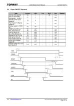
TOPWAY LCD Module User Manual LMT080TDGP01 TOPWAY LCD Module User Manual LMT080TDGP01
Open the catalog to page 6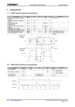
TOPWAY LCD Module User Manual LMT080TDGP01 5.2 LVDS mode AC electrical characteristics Parameter
Open the catalog to page 7
7.2 Data input format 7.2.1 LVDS data mapping G-bit LVDS input (SELB= "H" ) -1 Cycle- RMNtt* R3QMQ-RX1M1+ RMN1-RX1M2+ rxjws- X R[1] G[Q] YJwXRM1 X R[3]X R[2]X RniX^^K G[Q1X X Gp] X^HTX ijjJXjaX g[5j X XX X gp] XB^] X x^rx^Biarjroix^^^ ££ T ?? 8-bit LVDS input (SELB - x R[^x^niv gm x Rt5i x Rt4i x ^ x x r^i x i x /gpTXG[i] X XwX Q[S] X^XW^X^l Bl1i x X B[3] X B[2j X DE X^TX X 9[51~X BpTyipTX B[2} xDE X X Rt7i X^T)'j - X b^j X Bts: X X G[6] X *h X Rw % - X
Open the catalog to page 8
TOPWAY LCD Module User Manual LMT080TDGP01 Note: *1. Definition of optical measurement system. The optical characteristics should be measured in dark room. After 5 Minutes operation, the optical properties are measured at the center
Open the catalog to page 9
TOPWAY LCD Module User Manual LMT080TDGP01 *3.Definition of contrast ratio. Luminance measured when LCD is on the11White" state Contrast ratio (CR) = -:--—;-. -;————- Luminance measured when LCD is on the Black state “White state”: The state is that the LCD should drive by Vwhite. “Black state”: The state is that the LCD should drive by Vblack. Vwhite: To be determined Vblack: To be determined. *4.Definition of Response tim The response time is defined as the LCD optical switching time interval between “White” state and “Black” state. Rise time (Ton) is the time between photo detector output...
Open the catalog to page 10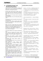
LCD Module User Manual 8. LCD Module Design and Handling Precautions Please ensure V0, VCOM is adjustable, to enable LCD module get the best contrast ratio under different temperatures, view angles and positions. Normally display quality should be judged under the best contrast ratio within viewable area. Unexpected display pattern may come out under abnormal contrast ratio. Never operate the LCD module exceed the absolute maximum ratings. Never apply signal to the LCD module without power supply. Keep signal line as short as possible to reduce external noise interference. IC chip (e.g. TAB or...
Open the catalog to page 11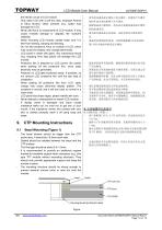
LCD Module User Manual the electric circuit of LCD module. Only clean LCD with a soft dry cloth, Isopropyl Alcohol or Ethyl Alcohol. Other solvents (e.g. water) may damage the LCD. Never add force to components of LCD module. It may cause invisible damage or degrade the module's reliability. When mounting LCD module, please make sure it is free from twisting, warping and bending. Do not add excessive force on surface of LCD, which may cause the display color change abnormally. LCD panel is made with glass. Any mechanical shock (e.g. dropping from high place) will damage the LCD module. Protective...
Open the catalog to page 12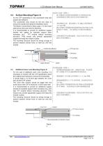
LCD Module User Manual Surface Mounting (Figure 2) As the CTP assembling on the countersink area with double side adhesive. The countersink area should be flat and clean to ensure the double side adhesive installation result. The Bezel is recommend to keep a gap (≥0.3mm each side) around the cover lens for tolerance. It is recommended to provide an additional support bracket with gasket for backside support when necessary (e.g. TFT module without mounding structure). They should only provide appropriate support and keep the module in place. The mounting structure should be strong enough to prevent...
Open the catalog to page 13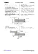
LCD Module User Manual It should bezel touching the RTP Active Area (A.A.) to prevent abnormal touch.It should left gab D=0.2~0.3mm in between. (Figure 4) Outer bezel design should take care about the area outside the A.A. Those areas contain circuit wires which is having different thickness. Touching those areas could de-form the ITO film. As a result bezel the ITO film be damaged and shorten its lifetime. It is suggested to protect those areas with gasket (between the bezel and RTP).The suggested figures are B≥0.50mm; C≥0.50mm. (Figure 4) The bezel side wall should keep space E= 0.2 ~ 0.3mm...
Open the catalog to page 14
LCD Module User Manual Warranty This product has been manufactured to our company’s specifications as a part for use in your company’s general electronic products. It is guaranteed to perform according to delivery specifications. For any other use apart from general electronic equipment, we cannot take responsibility if the product is used in medical devices, nuclear power control equipment, aerospace equipment, fire and security systems, or any other applications in which there is a direct risk to human life and where extremely high levels of reliability are required. If the product is to be...
Open the catalog to page 15All TOPWAY LCD catalogs and technical brochures
 TOPWAY Smart LCD SGTools Handbook
108 Pages
 10.1" TFT LCD Module
1 Page
 MONO Product
2 Pages
 LMT050DNCFWU-NNA-2
15 Pages
 HKT035BTB-1D
36 Pages
 HMT050AMC-C
17 Pages
 HMT043ATA-6C
31 Pages
 TM035PDHG09
42 Pages
 TM035PDHG03
31 Pages
 TM028HDZP01
28 Pages
 LM256160DCW-1
14 Pages
 LM12896FCW-1
17 Pages
 LM12832KCW
13 Pages
 LM2088EFW-9
12 Pages
 LM3122AGG-2
12 Pages
 LM240160YCW
18 Pages
 LM6093ACW
14 Pages
 HMT104ATA-C
11 Pages
 HMT101ATA-D
36 Pages
 HKT080ATA-C
1 Page
 HMT080ATA
1 Page
 HKT070DTA-1C
11 Pages
 HMT070DTA-D
1 Page
 HKT070DMC-2C
19 Pages
 HMT070ETD-C
31 Pages
 HMT070ETD-1D
34 Pages
 HMT056ATA-C
1 Page
 HMT050CB-1C
31 Pages
 HMT050DTA-D
1 Page
 HKT050ATA-C
1 Page
 HMT043ATA-7C
32 Pages
 HMT043GTA-1D
37 Pages
 HKT043BMC-2C
17 Pages
 HMT043ATA-3C
11 Pages
 HMT043BMC-C
1 Page
 HMT043ATA-4C
11 Pages
 HKT043BMC-C
1 Page
 HKT043ATA-1C
12 Pages
 HMT035ATA-D
13 Pages
 HMT028ATB-C
12 Pages
 HKT104ATA-C
31 Pages
 HMT068BTA-C
33 Pages
 HMT070ATA-1C
32 Pages
 HMT080ATA-C
33 Pages
 HMT090ATA-C
30 Pages
 HMT101ATA-C
33 Pages
 HMT050ATA-2C
31 Pages
 HMT043ATA-2C
32 Pages
 IC Raio RA6963 LCD Controller
42 Pages
 IC Epson S1D13L01 LCD Controller
118 Pages
 IC EPSON S1D13700 LCD Controller
133 Pages
 EPSON S1D13709 LCD Controller
192 Pages
 Samsung S6B0108 LCD Driver
23 Pages
 Avant SBN0064G LCD Driver
37 Pages
 Avant SBN6400G LCD Driver
34 Pages
 EPSON SED1335 LCD Controller
95 Pages
 SGS-THOMSON ST7282
23 Pages
 Raio RA6963 LCD Controller
42 Pages
 Raio RA8875 TFT LCD Controller
174 Pages
 Raio RA8835 LCD Controller
93 Pages
 RAIO RA8803 LCD Controller
8 Pages
 HMT035ATA-1C
1 Page
 Smart LCD introduction
14 Pages
 Topway company introduction
14 Pages
 TFT module in bezel
1 Page
 Topway TFT LCD
1 Page
 LM12864L Series
1 Page
 LM12864T Series
1 Page
 LM12864F Series
1 Page
 LM6060C Series
1 Page
 LM12864M Series
1 Page
 LM6029A Series
1 Page
 LM6059B Series
1 Page
 LM24048A Series
1 Page
 LM13232A Series
1 Page
 LM160160A Series
1 Page
 LMB402C Series
1 Page
 LMB242A Series
1 Page
 LMB204C Series
1 Page
 LM3121 Series
1 Page
 LMB404A Series
1 Page
 HMT043FC-1C
1 Page
 LM3123 Series
1 Page
 LMB204B Series
1 Page
 LMB202E Series
1 Page
 LMB202D Series
1 Page
 LMB164A Series
1 Page
 LMB162G Series
1 Page
 LMB162H Series
1 Page
 LMB162N Series
1 Page
 LMB162A Series
1 Page
 LMB0820D Series
1 Page
 LMB0820C Series
1 Page
 LMB0820A Series
1 Page
 LMB081N Series
1 Page
 LMB081A Series
1 Page
 LMB162X series
1 Page
 LMT057DNAFWU-AAN series
1 Page
 LMT057DNAFWU-AAA series
1 Page
 LMT104SDH01 Series
1 Page
 TOPWAY Product List (Y2012)
4 Pages
 TFT LCD module
1 Page
 Without controller
1 Page
 Chinese fonts
1 Page
 Built-in controller
1 Page
 Character module
1 Page



- LCD display panel
- Touch monitor
- LCD screen
- Industrial monitor
- HDMI monitor
- Industrial display panel
- VESA mounting monitor
- TFT display module
- Color display panel
- Touch screen display panel
- LED display panel
- High-brightness monitor
- IPS display panel
- Control display system
- Electronic display panel
- Backlit display panel
- TFT-LCD monitor
- Wall-mount monitor
- LED-backlit display panel