- Catalogs
- TOPWAY LCD
- LMT050DNCFWU-NNA-2
- Company
- Products
- Catalogs
- News & Trends
- Exhibitions
LMT050DNCFWU-NNA-2
1 /15Pages

LMT050DNCFWU-NNA-2
1 /15Pages
Catalog excerpts

LMT050DNCFWU-NNA-2LCD Module User Manual Prepared by: Document Name: LMT050DNCFWU-NNA-2-Manual-Rev0.2.doc Page: 1 of 14
Open the catalog to page 1
LCD Module User Manual
Open the catalog to page 2
TOPWAY LCD Module User Manual LMT050DNCFWU-NNA-2 TOPWAY LCD Module User Manual LMT050DNCFWU-NNA-2 5.0 inch 800 x 480 24bit parallel interface 16.7M color (24bit) 0.135x0.135 (mm) RGB Stripe Transmissive / normal white Anti-Glare Treatment 6H (*1) (gray scale inverse) 12H (*2) 120.7x75.8x4.1 (mm) (exclude FPC, see attached drawing for details) 108x64.8 (mm) LED -20 ~ +70°C -30 ~ +80°C 1. General Specification Screen Size(Diagonal): Resolution : Signal Interface : Color Depth : Pixel Pitch : Pixel Configuration : Display Mode : Surface Treatment: Viewing Direction : Outline Dimension : Active Area...
Open the catalog to page 3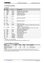
TOPWAY LCD Module User Manual LMT050DNCFWU-NNA-2 Note: 1. Interface : DE mode (default); 2. In DE mode, the 32 and 33 pins pass the pull-up resistance to 3.3V . 3. Absolute Maximum Rating w Cautions: Any Stresses exceeding the Absolute Maximum Ratings may cause substantial damage to the device. Functional operation of this device at other conditions beyond those listed in the specification is not implied and prolonged exposure to extreme conditions may affect device reliability. Document Name: LMT050DNCFWU-NNA-2-Manual-Rev0.2.doc Page: 4 of 14
Open the catalog to page 4
TOPWAY LCD Module User Manual LMT050DNCFWU-NNA-2 Note: Exceeding the recommended driving current could cause substantial damage to the backlight and shorten its lifetime. tHHf-W-W-N-W VLED- Document Name: LMT050DNCFWU-NNA-2-Manual-Rev0.2.doc Page: 5 of 14
Open the catalog to page 5
LCD Module User Manual 4.4 Power ON/OFF Sequence Power On/Off Sequence Document Name: LMT050DNCFWU-NNA-2-Manual-Rev0.2.doc Page: 6 of 14
Open the catalog to page 6
TOPWAY LCD Module User Manual LMT050DNCFWU-NNA-2 Document Name: LMT050DNCFWU-NNA-2-Manual-Rev0.2.doc Page: 7 of 14
Open the catalog to page 7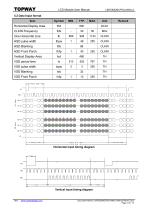
TOPWAY LCD Module User Manual LMT050DNCFWU-NNA-2 5.2 Data Input format Document Name: LMT050DNCFWU-NNA-2-Manual-Rev0.2.doc Page: 8 of 14
Open the catalog to page 8
TOPWAY LCD Module User Manual LMT050DNCFWU-NNA-2 Test Conditions: 1. IF= 40mA, VF=21.7V, and the ambient temperature is 25. °C 2. The test systems refer to Note 1 and Note 2. Document Name: LMT050DNCFWU-NNA-2-Manual-Rev0.2.doc Page: 9 of 14
Open the catalog to page 9
LCD Module User Manual Note 1: The data are measured after LEDs are turned on for 5 minutes. LCM displays full white. The brightness is the average value of 9 measured spots. Measurement equipment SR-3A (1°) Measuring condition: - Measuring surroundings: Dark room - Measuring temperature: Ta=25℃. - Adjust operating voltage to get optimum contrast at the center of the display. Note 3: The definition of contrast ratio (Test LCM using SR-3A (1°)): Luminance When LCD is at “White” state Contrast = Ratio(CR) Luminance When LCD is at “Black” state (Contrast Ratio is measured in optimum common electrode...
Open the catalog to page 10
LCD Module User Manual 7. 液晶显示模块设计和使用须知 7. LCD Module Design and Handling Precautions - Please ensure V0, VCOM is adjustable, to enable LCD - 请注意 V0, VCOM 的设定, 以确保液晶显示模块在不同 module get the best contrast ratio under different temperatures, view angles and positions. Normally display quality should be judged under the best contrast ratio within viewable area. Unexpected display pattern may com out under abnormal contrast ratio. Never operate the LCD module exceed the absolute maximum ratings. Never apply signal to the LCD module without power supply. Keep signal line as short as possible to reduce...
Open the catalog to page 11
LCD Module User Manual Only clean LCD with a soft dry cloth, Isopropyl Alcohol or Ethyl Alcohol. Other solvents (e.g. water) may damage the LCD. Never add force to components of LCD module. It may cause invisible damage or degrade the module's reliability. When mounting LCD module, please make sure it is free from twisting, warping and bending. Do not add excessive force on surface of LCD, which may cause the display color change abnormally. LCD panel is made with glass. Any mechanical shock (e.g. dropping from high place) will damage the LCD module. Protective film is attached on LCD screen....
Open the catalog to page 12
LCD Module User Manual The countersink area should be flat and clean to ensure the double side adhesive installation result. The Bezel is recommend to keep a gap (≥0.3mm each side) around the cover lens for tolerance. It is recommended to provide an additional support bracket with gasket for backside support when necessary (e.g. TFT module without mounding structure). They should only provide appropriate support and keep the module in place. The mounting structure should be strong enough to prevent external uneven force or twist act onto the module Figure 2 8.3 Additional Cover Lens Mounting...
Open the catalog to page 13
LCD Module User Manual It is suggested to protect those areas with gasket (between the bezel and RTP).The suggested figures are B≥0.50mm; C≥0.50mm. (Figure 4) The bezel side wall should keep space E= 0.2 ~ 0.3mm from the RTP. (Figure 4) 动作区的边缘,面框边缘到 V.A.区的距离 B≥0.50mm; 垫圈内边缘到 V.A.区的距离 C≥0.50mm. (附图 4) 在设计面框与 RTP 组装时,应考虑到面框内侧与 RTP 外 侧的间距 E≥0.2mm. (附图 4) 通常设计时: RTP 的可视区 V.A. 应不小于 TFT 的可视区 V.A. 及 RTP 的动作区 A.A. 应不小于 TFT 的动作区 A.A. (附图 5) In general design, RTP V.A. should be bigger than the TFT V.A. and RTP A.A. should be bigger than the TFT A.A. (Figure 5) Warranty This product has been manufactured...
Open the catalog to page 14
Note; *1, LCD Display Type; TFT.Transnissive *2, Pixel Arrangmenti RGB-SPRIPE *3, Color Depth : 16M (24bit) color *4, Operating Voltage : 3,3V *5, Backlight Supply •• 40mA (Constant Current 21,7V TYP) *6, Backlight : LED *7, Touch Panel Type : Resistive Touch Panel *8, Eoan Gasket must be assemble outside TP VA by 0,5mm *9, Operating Temperatune : -20<>C~70<>C *10, Storage Temperature •• -30*^80*3 *11, Unmarked Tolerance : ^150,±0,3j >150,±0,5 Touch Panel Logic Details Scale=f ree
Open the catalog to page 15All TOPWAY LCD catalogs and technical brochures
 TOPWAY Smart LCD SGTools Handbook
108 Pages
 10.1" TFT LCD Module
1 Page
 MONO Product
2 Pages
 LMT080TDGP01
16 Pages
 HKT035BTB-1D
36 Pages
 HMT050AMC-C
17 Pages
 HMT043ATA-6C
31 Pages
 TM035PDHG09
42 Pages
 TM035PDHG03
31 Pages
 TM028HDZP01
28 Pages
 LM256160DCW-1
14 Pages
 LM12896FCW-1
17 Pages
 LM12832KCW
13 Pages
 LM2088EFW-9
12 Pages
 LM3122AGG-2
12 Pages
 LM240160YCW
18 Pages
 LM6093ACW
14 Pages
 HMT104ATA-C
11 Pages
 HMT101ATA-D
36 Pages
 HKT080ATA-C
1 Page
 HMT080ATA
1 Page
 HKT070DTA-1C
11 Pages
 HMT070DTA-D
1 Page
 HKT070DMC-2C
19 Pages
 HMT070ETD-C
31 Pages
 HMT070ETD-1D
34 Pages
 HMT056ATA-C
1 Page
 HMT050CB-1C
31 Pages
 HMT050DTA-D
1 Page
 HKT050ATA-C
1 Page
 HMT043ATA-7C
32 Pages
 HMT043GTA-1D
37 Pages
 HKT043BMC-2C
17 Pages
 HMT043ATA-3C
11 Pages
 HMT043BMC-C
1 Page
 HMT043ATA-4C
11 Pages
 HKT043BMC-C
1 Page
 HKT043ATA-1C
12 Pages
 HMT035ATA-D
13 Pages
 HMT028ATB-C
12 Pages
 HKT104ATA-C
31 Pages
 HMT068BTA-C
33 Pages
 HMT070ATA-1C
32 Pages
 HMT080ATA-C
33 Pages
 HMT090ATA-C
30 Pages
 HMT101ATA-C
33 Pages
 HMT050ATA-2C
31 Pages
 HMT043ATA-2C
32 Pages
 IC Raio RA6963 LCD Controller
42 Pages
 IC Epson S1D13L01 LCD Controller
118 Pages
 IC EPSON S1D13700 LCD Controller
133 Pages
 EPSON S1D13709 LCD Controller
192 Pages
 Samsung S6B0108 LCD Driver
23 Pages
 Avant SBN0064G LCD Driver
37 Pages
 Avant SBN6400G LCD Driver
34 Pages
 EPSON SED1335 LCD Controller
95 Pages
 SGS-THOMSON ST7282
23 Pages
 Raio RA6963 LCD Controller
42 Pages
 Raio RA8875 TFT LCD Controller
174 Pages
 Raio RA8835 LCD Controller
93 Pages
 RAIO RA8803 LCD Controller
8 Pages
 HMT035ATA-1C
1 Page
 Smart LCD introduction
14 Pages
 Topway company introduction
14 Pages
 TFT module in bezel
1 Page
 Topway TFT LCD
1 Page
 LM12864L Series
1 Page
 LM12864T Series
1 Page
 LM12864F Series
1 Page
 LM6060C Series
1 Page
 LM12864M Series
1 Page
 LM6029A Series
1 Page
 LM6059B Series
1 Page
 LM24048A Series
1 Page
 LM13232A Series
1 Page
 LM160160A Series
1 Page
 LMB402C Series
1 Page
 LMB242A Series
1 Page
 LMB204C Series
1 Page
 LM3121 Series
1 Page
 LMB404A Series
1 Page
 HMT043FC-1C
1 Page
 LM3123 Series
1 Page
 LMB204B Series
1 Page
 LMB202E Series
1 Page
 LMB202D Series
1 Page
 LMB164A Series
1 Page
 LMB162G Series
1 Page
 LMB162H Series
1 Page
 LMB162N Series
1 Page
 LMB162A Series
1 Page
 LMB0820D Series
1 Page
 LMB0820C Series
1 Page
 LMB0820A Series
1 Page
 LMB081N Series
1 Page
 LMB081A Series
1 Page
 LMB162X series
1 Page
 LMT057DNAFWU-AAN series
1 Page
 LMT057DNAFWU-AAA series
1 Page
 LMT104SDH01 Series
1 Page
 TOPWAY Product List (Y2012)
4 Pages
 TFT LCD module
1 Page
 Without controller
1 Page
 Chinese fonts
1 Page
 Built-in controller
1 Page
 Character module
1 Page


- Monitor with touchscreen
- Industrial monitor
- HDMI monitor
- VESA mounting monitor
- Industrial display panel
- TFT display module
- IP65 monitor
- Touch screen display panel
- Color display panel
- LED display panel
- High-brightness monitor
- TFT-LCD monitor
- Electronic display panel
- Control display system
- Wall-mount monitor
- IPS display panel
- Backlit display panel
- Programmable display system