- Catalogs
- TOPWAY LCD
- ILITEK ILI2511 Single Chip Capacitive Touch Sensor Controller
- Company
- Products
- Catalogs
- News & Trends
- Exhibitions
ILITEK ILI2511 Single Chip Capacitive Touch Sensor Controller
1 /19Pages

ILITEK ILI2511 Single Chip Capacitive Touch Sensor Controller
1 /19Pages
Catalog excerpts

ILI2511 Single Chip Capacitive Touch Sensor Controller 8F., No.1, Taiyuan 2 St., Zhubei City, Hsinchu County 302, Taiwan (R.O.C.) Tel.886-3-5600099; Fax.886-3-5600055 http://www.ilitek.com
Open the catalog to page 1
Capacitive Touch Sensor Controller Revision History Version Description Preliminary released Modify the pin description & application circuit. Modify the pin assignment & pin description. Modify the page information of revision history. Modify the feature and application circuit. Modify VDDIO operation voltage Modify Power Sequence Modify Recommended Operating Conditions, DC Characteristics, I2C DC Characteristics Final Specification released Change VDDIO From 5V into 3.3V Add VDDIO 3.3V or 1.8V Input Power Supply Characteristics Add Marking Information Modify Input Power Supply Voltage Range...
Open the catalog to page 2
Capacitive Touch Sensor Controller
Open the catalog to page 3
Capacitive Touch Sensor Controller 1. Description The ILI2511 is a single chip capacitive touch sensor controller optimized for POS, ATM and Industry Capacitive Touch Panel applications. It integrates high speed Capacitance to Digital Converter (CDC), total 65 channels including high voltage Driving and Sensing channels, high voltage Charge Pump Controller , high voltage regulator and 32-bit high performance Micro-controller (MCU). With compact QFN-88 package, its package size is 10mm*10mm*1mm and pad pitch is 0.4mm. ILI2511 meets all Windows 8.1 and Windows 10 requirements with best user touch...
Open the catalog to page 4
Capacitive Touch Sensor Controller HV Charge Pump OSC XTAL PLL Figure 3-1: ILI2511 Block Diagram
Open the catalog to page 5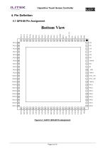
Capacitive Touch Sensor Controller
Open the catalog to page 6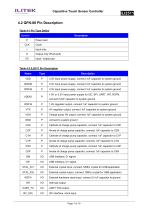
Capacitive Touch Sensor Controller 4.2 QFN-88 Pin Description Table 4-1 Pin Type Define Symbol P CLK Description Power pad Clock Input only Output only (Push-pull) Table 4-2 ILI2511 Pin Description Name 3.3V input power supply, connect 1uF capacitor to system ground 3.3V input power supply, connect 1uF capacitor to system ground 3.3V input power supply, connect 1uF capacitor to system ground 1.6V regulator output, connect 1uF capacitor to system ground HV regulator output, connect 1uF capacitor to system ground Charge pump HV output, connect 1uF capacitor to system ground connect to system ground...
Open the catalog to page 7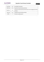
Capacitive Touch Sensor Controller I2C interface, data input. Typical touch panel sensing channels Typical touch panel sensing channels and can be configured to driving channels Typical touch panel driving channels connect to system ground
Open the catalog to page 8
Capacitive Touch Sensor Controller 5. Electrical Characteristics 5.1 Absolute Maximum Ratings Stresses beyond those listed under “Absolute Maximum Ratings” may cause permanent damage to the device. These are for stress ratings. Functional operation of the device at these or any other conditions beyond those indicated in the operational sections of the specifications is not implied. Exposure to absolute maximum rating conditions for extended periods may remain possibility to affect device reliability. Table 5-1: Absolute Maximum Ratings Chip power input ESD Susceptibility HBM (Human Body Mode)(Note...
Open the catalog to page 9
Capacitive Touch Sensor Controller 5.2 Recommended Operating Conditions Table 5-2: Recommended Operating Conditions Operating Ambient Temperature Range Operating Junction Temperature Range Storage Ambient Temperature Range VDD to GND input power supply voltage Note: The device is not guaranteed to function outside its operating conditions.
Open the catalog to page 10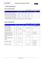
Capacitive Touch Sensor Controller 5.3 DC Characteristics Table 5-3: Input Power Supply (VDD3A=VDD3D=3.3V, Room Temperature) Item Digital input power supply voltage* Analog input power supply voltage 3.3V I/O input power supply voltage* 1.8V I/O input power supply voltage* *If VDDIO & VDD3D is not supplied power, there is risk of I/O pin with current leakage Table 5-4: DC Characteristics (VDD3A=VDD3D=3.3V, Room Temperature) Item Operation current Input High Voltage Hysteresis voltage Input Low Voltage, XT_In Input High Voltage, XT_In Output High Voltage /Reset Positive going threshold, /Reset...
Open the catalog to page 11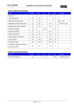
Capacitive Touch Sensor Controller Table 5-5: USB DC Characteristics Item Input High (driven) Differential input sensitivity Differential common-mode range Single-ended receiver threshold Receiver hysteresis Output high (driven) Output signal cross voltage Pull-up resistor Pull-down resistor Termination Voltage for upstream port pull up (RPU) Table 5-6: Crystal Characteristics Item Input clock frequency Condition External crysta
Open the catalog to page 12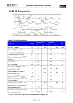
Capacitive Touch Sensor Controller Table 5-7: I2C AC Characteristics Parameter HIGH period of the SCL clock Data hold time Data set-up time START condition Capacitive load for each bus line SCL clock frequency Hold time START condition Set-up time for a repeated START Rise time of both SDA and SCL signals (30% to 70%) Fall time of both SDA and SCL signals (70% to 30%) Set-up time for STOP condition Bus free time between a STOP and Noise margin at the LOW level for each connected device Noise margin at the HIGH level for each connected device *SCL = I2C Host must to support clock stretching mode...
Open the catalog to page 13
Capacitive Touch Sensor Controller 6. Power Sequence 6.1 Power-on Sequence V Start to report location By USB or I2C 1. T1: the time difference between 0.9*VDD and 0.9*VDDIO. T1 must be ≥ 0 sec. 2. T2: the time difference between 0.9*VDDIO and RSTN. T2 must be ≥ 200 us. 3. T3: the time difference between RSTN and Commands.T3 must be ≥ 150 ms. 4. T4: IC start to report point location to host. T4 must be ≥ 300 ms.
Open the catalog to page 14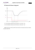
Capacitive Touch Sensor Controller 6.2 Power-off to Power-on Sequence V Tg1 : the time difference between power-off and power-on. Tg1 must be > 10us. Tg2 : the time difference between power-off and power-on. Tg2 must be > 10us. Note. During the power off time, the VDD must be lower than 0.5V that make sure the touch controller have been correctly reset.
Open the catalog to page 15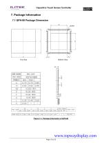
Capacitive Touch Sensor Controller 7. Package Information 7.1 QFN-88 Package Dimension Bottom View Figure 7-1: Package Information of QFN-88
Open the catalog to page 16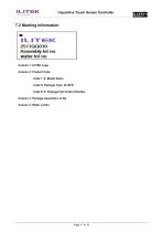
Capacitive Touch Sensor Controller Column 1: ILITEK Logo Column 2: Product Code Code 1~4: Model Name Code 5: Package Type, Q: QFN Code 6~9: Package Fab Control Number Column 3: Package Assembly Lot No Column 4: Wafer Lot No
Open the catalog to page 17All TOPWAY LCD catalogs and technical brochures
 TOPWAY Smart LCD SGTools Handbook
108 Pages
 10.1" TFT LCD Module
1 Page
 MONO Product
2 Pages
 LMT050DNCFWU-NNA-2
15 Pages
 LMT080TDGP01
16 Pages
 HKT035BTB-1D
36 Pages
 HMT050AMC-C
17 Pages
 HMT043ATA-6C
31 Pages
 TM035PDHG09
42 Pages
 TM035PDHG03
31 Pages
 TM028HDZP01
28 Pages
 LM256160DCW-1
14 Pages
 LM12896FCW-1
17 Pages
 LM12832KCW
13 Pages
 LM2088EFW-9
12 Pages
 LM3122AGG-2
12 Pages
 LM240160YCW
18 Pages
 LM6093ACW
14 Pages
 HMT104ATA-C
11 Pages
 HMT101ATA-D
36 Pages
 HKT080ATA-C
1 Page
 HMT080ATA
1 Page
 HKT070DTA-1C
11 Pages
 HMT070DTA-D
1 Page
 HKT070DMC-2C
19 Pages
 HMT070ETD-C
31 Pages
 HMT070ETD-1D
34 Pages
 HMT056ATA-C
1 Page
 HMT050CB-1C
31 Pages
 HMT050DTA-D
1 Page
 HKT050ATA-C
1 Page
 HMT043ATA-7C
32 Pages
 HMT043GTA-1D
37 Pages
 HKT043BMC-2C
17 Pages
 HMT043ATA-3C
11 Pages
 HMT043BMC-C
1 Page
 HMT043ATA-4C
11 Pages
 HKT043BMC-C
1 Page
 HKT043ATA-1C
12 Pages
 HMT035ATA-D
13 Pages
 HMT028ATB-C
12 Pages
 HKT104ATA-C
31 Pages
 HMT068BTA-C
33 Pages
 HMT070ATA-1C
32 Pages
 HMT080ATA-C
33 Pages
 HMT090ATA-C
30 Pages
 HMT101ATA-C
33 Pages
 HMT050ATA-2C
31 Pages
 HMT043ATA-2C
32 Pages
 IC Raio RA6963 LCD Controller
42 Pages
 IC Epson S1D13L01 LCD Controller
118 Pages
 IC EPSON S1D13700 LCD Controller
133 Pages
 EPSON S1D13709 LCD Controller
192 Pages
 Samsung S6B0108 LCD Driver
23 Pages
 Avant SBN0064G LCD Driver
37 Pages
 Avant SBN6400G LCD Driver
34 Pages
 EPSON SED1335 LCD Controller
95 Pages
 SGS-THOMSON ST7282
23 Pages
 Raio RA6963 LCD Controller
42 Pages
 Raio RA8875 TFT LCD Controller
174 Pages
 Raio RA8835 LCD Controller
93 Pages
 RAIO RA8803 LCD Controller
8 Pages
 HMT035ATA-1C
1 Page
 Smart LCD introduction
14 Pages
 Topway company introduction
14 Pages
 TFT module in bezel
1 Page
 Topway TFT LCD
1 Page
 LM12864L Series
1 Page
 LM12864T Series
1 Page
 LM12864F Series
1 Page
 LM6060C Series
1 Page
 LM12864M Series
1 Page
 LM6029A Series
1 Page
 LM6059B Series
1 Page
 LM24048A Series
1 Page
 LM13232A Series
1 Page
 LM160160A Series
1 Page
 LMB402C Series
1 Page
 LMB242A Series
1 Page
 LMB204C Series
1 Page
 LM3121 Series
1 Page
 LMB404A Series
1 Page
 HMT043FC-1C
1 Page
 LM3123 Series
1 Page
 LMB204B Series
1 Page
 LMB202E Series
1 Page
 LMB202D Series
1 Page
 LMB164A Series
1 Page
 LMB162G Series
1 Page
 LMB162H Series
1 Page
 LMB162N Series
1 Page
 LMB162A Series
1 Page
 LMB0820D Series
1 Page
 LMB0820C Series
1 Page
 LMB0820A Series
1 Page
 LMB081N Series
1 Page
 LMB081A Series
1 Page
 LMB162X series
1 Page
 LMT057DNAFWU-AAN series
1 Page
 LMT057DNAFWU-AAA series
1 Page
 LMT104SDH01 Series
1 Page
 TOPWAY Product List (Y2012)
4 Pages
 TFT LCD module
1 Page
 Without controller
1 Page
 Chinese fonts
1 Page
 Built-in controller
1 Page
 Character module
1 Page


- Display module
- Monitor with touchscreen
- Industrial monitor
- LCD display panel
- HDMI monitor
- VESA mounting monitor
- Industrial display panel
- TFT display module
- IP65 monitor
- Touch screen display panel
- Color display panel
- LED display panel
- High-brightness monitor
- TFT-LCD monitor
- Electronic display panel
- Control display system
- Wall-mount monitor
- IPS display panel
- Backlit display panel
- Programmable display system