
- Catalogs
- TOPWAY LCD
- HMT050ATA-2C


- Company
- Products
- Catalogs
- News & Trends
- Exhibitions
HMT050ATA-2C

HMT050ATA-2C
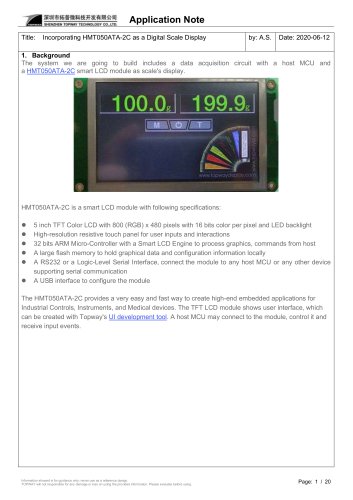
The TOPWAY HMT050ATA-2C is a Smart TFT Module with a 32-bit MCU and graphics engine supporting TOPWAY TML 3.0, suitable for industrial, medical, and power electronics applications. It features a 5.0” screen, 800x480 resolution, 65k color depth, and operates between -20 to +70°C.
Power supply voltage ranges from -0.3 to 26.0 V. Operating and storage temperatures are -20 to 70°C and -30 to 80°C, respectively. Exceeding these limits may cause damage.
Operates at 5.0 to 26.0 V with typical currents of 180 mA for VDD and 175 mA for USB.
Supports TML, picture, and ICON files in FLASH memory, with real-time access via UART and custom memory access by the HOST.
Viewing angle is 60-70 degrees, contrast ratio is 400-500, with response times of 10-20 msec for Tf and 15-30 msec for Tr.
Ensure adjustable V0 and VCOM for contrast, avoid exceeding maximum ratings, and maintain a static-free environment. Store at 0-40°C and <80% RH, away from sunlight and harmful gases.
Bezel window should be larger than the CTP active area with a gasket between bezel and CTP. Support brackets are recommended for slim modules.
7.1 Front Frame Installation
- Front frame window should be larger than CTP active area, with a 0.5mm gap.
- Gasket between frame and CTP panel, with a 0.5-1.0mm gap.
- Support brackets recommended for thin modules.
- Mounting structure must prevent external forces.
- CTP assembled on a flat, clean area with adhesive.
- Maintain a 0.3mm gap around cover lens.
- Support brackets recommended for backside support.
- Check CTP specifications for material and thickness.
- Maintain a 0.2-0.3mm gap between cover lens and CTP.
- Support brackets recommended for backside support.
- Maintain a 0.2-0.3mm gap between bezel and RTP active area.
- Protect areas outside active area to prevent damage.
- Gaskets recommended between bezel and RTP.
- RTP visible area should be larger than TFT visible area.
- Product guaranteed to perform according to specifications.
- No responsibility for defects from additional manufacturing or external forces.
- Separate liability agreement required for critical applications.
- Color Data Value Configuration: 16-bit color values arranged with red, green, and blue components.
- Data/Address/Page_ID/Location Values Configuration: Arrangement of 64-bit, 32-bit, and 16-bit values from MSB to LSB.
- Command Table: Lists functions with codes and descriptions, including configuration/status, display control, and VP functions.
- Specific Commands:
- hand_shake (0x30): Initiates handshake.
- read_version (0x31): Reads firmware version.
- touch_response (0x72/0x73/0x77/0x78/0x79): Handles touch panel responses.
- set_sys_config (0xE0): Configures system parameters.
- Flash_write (0x90) and Flash_read (0x91): Handle flash memory operations.
- Read USR_bin Data (0x93): Reads data from flash memory.
- Successive Write (0x82) and Read (0x83): Handle successive value operations.
- U_drv_format (0xE2): Formats USB drive.
- U_drv_unlock (0xE3): Unlocks USB drive for operations.
- Display Page (0x70): Displays TML file.
- Set Element Foreground (0x7E) and Background (0x7F): Set display element colors.
- System Register Write (0x3B) and Read (0x3C): Handle system register operations.
- G16 Write (0x4D) and Rotate (0x4E): Write graph values with rotation options.
- N16 Write (0x3D), Read (0x3E), and Fill (0x3F): Handle 16-bit numbers.
Catalog excerpts

HMT050ATA-2C LCD Module User Manual Release Date - Preliminary Draft release -Update Section 1.3 ,Section 3.1 and Section 5 -Add Highlight Description www.topwaydisplay.com www.topwaysz.com Document Name: HMT050ATA-2C-Manual-Rev0.3.doc Page: 1 of 11
Open the catalog to page 1
LCD Module User Manual www.topwaydisplay.com www.topwaysz.com Document Name: HMT050ATA-2C-Manual-Rev0.3.doc Page: 2 of 11
Open the catalog to page 2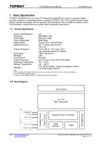
LCD Module User Manual 1 Basic Specification TOPWAY HMT050ATA-2C is a Smart TFT Module with 32bit MCU on board. Its graphics engine provides numbers of outstanding features. It supports TOPWAY TML 3.0 for preload and pre-design display interface that simplify the host operation and development time. Suitable for industry control, instrumentation, medical electronics, power electric equipment applications. General Specification Screen Size(Diagonal) : Resolution : Color Depth : Pixel Configuration : Display Mode : Viewing Direction : Outline Dimension : Active Area : Backlight : Command I/F: Project...
Open the catalog to page 3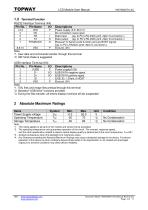
LCD Module User Manual Terminal Function RS232 Interface Terminal (K4) Pin No. Pin Name I/O 1,2,3 4 5 6 7 Descriptions Power supply (5.0~26.0 V) No connection, leave open Data Input (eg. to PC’s RS-232C pin3 <9pin D-connector>) Data output (eg. to PC’s RS-232C pin2 <9pin D-connector>) Request To Send (could function as busy BUSY signal) (eg. to PC’s RS232C pin8 <9pin D-connector>) Ground, (0V) Note. *1. User data and commands transfer through this terminal *2. HW hand shake is suggested USB Interface Terminal (K3) Pin No. Pin Name I/O 1 2 3 4 5 Descriptions Power supply(5.0V) USB DATA negative...
Open the catalog to page 4
LCD Module User Manual Items Symbol Operating Voltage Vdd RxD Input MARK(1) VRxDM RxD Input SPACE(0) VRXDS TxD Output MARK(1) VTXDM TxD Output SPACE(0) VTXDS RTS Output High VTXDH RTS Output Low VTXDL Operating Current IDD Operating Current (USB) IVUSB Battery Supply Current IBAT Note. *1. Normal display condition VSS=0V, VDD=12V, TOP =25C Unit Applicable Pin/FUNC V VDD V Rx V Rx V Tx V Tx V RTS(BUSY) V RTS(BUSY) mA VDD (*1) mA VUSB uA Function Specifications Basic Operation Function Descriptions TML files Picture files ICONS files UART interface Custom Memories Touch Panel Control and Draw...
Open the catalog to page 5
LCD Module User Manual Quick Start Guide Install TOPWAY Graphics Editor Import pictures 2. design UI flow Connect to host Show 5. real time data Command Descriptions Please refer to “SMART LCD Command Manual” www.topwaydisplay.com www.topwaysz.com Document Name: HMT050ATA-2C-Manual-Rev0.3.doc Page: 6 of 1
Open the catalog to page 6
LCD Module User Manual 5 Optical Characteristics Item Contrast ratio Color chromaticity Luminance Luminance uniformity Note: *1. Definition of Contrast Ratio The contrast ratio could be calculate by the following expression: Contrast Ratio (CR) = Luminance with all pixels white / Luminance with all pixels black *2 Definition of Viewing Angle *3 Definition of response time www.topwaydisplay.com www.topwaysz.com *4 Definition of Luminance Uniformity Luminance uniformity (Lu)= Min. Luminance form pt1~pt9 / Max Luminance form Pt1~pt9
Open the catalog to page 7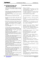
LCD Module User Manual 6 LCD Module Design and Handling Precautions Please ensure V0, VCOM is adjustable, to enable LCD module get the best contrast ratio under different temperatures, view angles and positions. Normally display quality should be judged under the best contrast ratio within viewable area. Unexpected display pattern may com out under abnormal contrast ratio. Never operate the LCD module exceed the absolute maximum ratings. Never apply signal to the LCD module without power supply. Keep signal line as short as possible to reduce external noise interference. IC chip (e.g. TAB or...
Open the catalog to page 8
LCD Module User Manual Protective film is attached on LCD screen. Be careful when peeling off this protective film, since static electricity may be generated. Polarizer on LCD gets scratched easily. If possible, do not remove LCD protective film until the last step of installation. When peeling off protective film from LCD, static charge may cause abnormal display pattern. The symptom is normal, and it will turn back to normal in a short while. LCD panel has sharp edges, please handle with care. Never attempt to disassemble or rework LCD module. If display panel is damaged and liquid crystal...
Open the catalog to page 9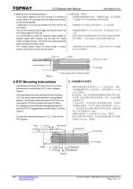
LCD Module User Manual 7.3 Additional Cover Lens Mounting (Figure 3) - For the case of additional cover Lens mounting, it is necessary to recheck with the CTP specification about the material and thickness to ensure the functionality. - It should keep a 0.2~0.3mm gap between the cover lens and the CTP surface.. - The cover lens window should be bigger than the active area of the CTP.It should be≥0.5mm each side. - It is recommended to provide an additional support bracket for backside support when necessary (e.g. slim type TFT module without mounding structure). They should only provide appropriate...
Open the catalog to page 10
LCD Module User Manual In general design, RTP V.A. should be bigger than the TFT V.A. and RTP A.A. should be bigger than the TFT A.A. (Figure 5) 通常设计时: RTP的可视区 V.A. 应不小于TFT 的可视区 V.A. 及RTP的动作区 A.A. 应不小于TFT 的动作区 A.A. (附图5) Warranty This product has been manufactured to our company’s specifications as a part for use in your company’s general electronic products. It is guaranteed to perform according to delivery specifications. For any other use apart from general electronic equipment, we cannot take responsibility if the product is used in medical devices, nuclear power control equipment, aerospace...
Open the catalog to page 11
SMART LCD Command V5.04 Manual Release Date - Preliminary Draft release - Add a description of the 0xE8 command - 4.1, 0xE2, 0xE3 command name correction - Add a description of the 0xE7 command Document Name:SMART LCD Command v5.04 Manual Rev0.4.doc Page: 1 of 19
Open the catalog to page 12
SMART LCD Command Manual Document Name:SMART LCD Command v5.04 Manual Rev0.4.doc Page: 2 of 19
Open the catalog to page 13
SMART LCD Command Manual 1 Basic Specifications TOPWAY Smart LCD serial command is for real-time control and access. Host machine get the data which input through the Smart LCD interface or provide the data for display. Hardware connection Smart LCD serial UART interface are mainly base on RS232-C standard, by default, config as 8N1 115200bps. Communication Packet Structure Commands and Response Packet should be format as follow (hostmodule): Seq 1 2 Code type Packet header Command code Parameter or Data Packet tail Note. *1. Unless otherwise specified, all the multi-byte values, data, address’...
Open the catalog to page 14All TOPWAY LCD catalogs and technical brochures
 TOPWAY Smart LCD SGTools Handbook
108 Pages
 10.1" TFT LCD Module
1 Page
 MONO Product
2 Pages
 LMT050DNCFWU-NNA-2
15 Pages
 LMT080TDGP01
16 Pages
 HKT035BTB-1D
36 Pages
 HMT050AMC-C
17 Pages
 HMT043ATA-6C
31 Pages
 TM035PDHG09
42 Pages
 TM035PDHG03
31 Pages
 TM028HDZP01
28 Pages
 LM256160DCW-1
14 Pages
 LM12896FCW-1
17 Pages
 LM12832KCW
13 Pages
 LM2088EFW-9
12 Pages
 LM3122AGG-2
12 Pages
 LM240160YCW
18 Pages
 LM6093ACW
14 Pages
 HMT104ATA-C
11 Pages
 HMT101ATA-D
36 Pages
 HKT080ATA-C
1 Page
 HMT080ATA
1 Page
 HKT070DTA-1C
11 Pages
 HMT070DTA-D
1 Page
 HKT070DMC-2C
19 Pages
 HMT070ETD-C
31 Pages
 HMT070ETD-1D
34 Pages
 HMT056ATA-C
1 Page
 HMT050CB-1C
31 Pages
 HMT050DTA-D
1 Page
 HKT050ATA-C
1 Page
 HMT043ATA-7C
32 Pages
 HMT043GTA-1D
37 Pages
 HKT043BMC-2C
17 Pages
 HMT043ATA-3C
11 Pages
 HMT043BMC-C
1 Page
 HMT043ATA-4C
11 Pages
 HKT043BMC-C
1 Page
 HKT043ATA-1C
12 Pages
 HMT035ATA-D
13 Pages
 HMT028ATB-C
12 Pages
 HKT104ATA-C
31 Pages
 HMT068BTA-C
33 Pages
 HMT070ATA-1C
32 Pages
 HMT080ATA-C
33 Pages
 HMT090ATA-C
30 Pages
 HMT101ATA-C
33 Pages
 HMT043ATA-2C
32 Pages
 IC Raio RA6963 LCD Controller
42 Pages
 IC Epson S1D13L01 LCD Controller
118 Pages
 IC EPSON S1D13700 LCD Controller
133 Pages
 EPSON S1D13709 LCD Controller
192 Pages
 Samsung S6B0108 LCD Driver
23 Pages
 Avant SBN0064G LCD Driver
37 Pages
 Avant SBN6400G LCD Driver
34 Pages
 EPSON SED1335 LCD Controller
95 Pages
 SGS-THOMSON ST7282
23 Pages
 Raio RA6963 LCD Controller
42 Pages
 Raio RA8875 TFT LCD Controller
174 Pages
 Raio RA8835 LCD Controller
93 Pages
 RAIO RA8803 LCD Controller
8 Pages
 HMT035ATA-1C
1 Page
 Smart LCD introduction
14 Pages
 Topway company introduction
14 Pages
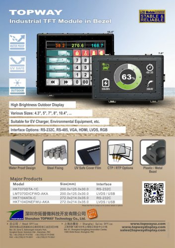 TFT module in bezel
1 Page
 Topway TFT LCD
1 Page
 LM12864L Series
1 Page
 LM12864T Series
1 Page
 LM12864F Series
1 Page
 LM6060C Series
1 Page
 LM12864M Series
1 Page
 LM6029A Series
1 Page
 LM6059B Series
1 Page
 LM24048A Series
1 Page
 LM13232A Series
1 Page
 LM160160A Series
1 Page
 LMB402C Series
1 Page
 LMB242A Series
1 Page
 LMB204C Series
1 Page
 LM3121 Series
1 Page
 LMB404A Series
1 Page
 HMT043FC-1C
1 Page
 LM3123 Series
1 Page
 LMB204B Series
1 Page
 LMB202E Series
1 Page
 LMB202D Series
1 Page
 LMB164A Series
1 Page
 LMB162G Series
1 Page
 LMB162H Series
1 Page
 LMB162N Series
1 Page
 LMB162A Series
1 Page
 LMB0820D Series
1 Page
 LMB0820C Series
1 Page
 LMB0820A Series
1 Page
 LMB081N Series
1 Page
 LMB081A Series
1 Page
 LMB162X series
1 Page
 LMT057DNAFWU-AAN series
1 Page
 LMT057DNAFWU-AAA series
1 Page
 LMT104SDH01 Series
1 Page
 TOPWAY Product List (Y2012)
4 Pages
 TFT LCD module
1 Page
 Without controller
1 Page
 Chinese fonts
1 Page
 Built-in controller
1 Page
 Character module
1 Page



- LCD display panel
- Touch monitor
- LCD screen
- Industrial monitor
- HDMI monitor
- Industrial display panel
- VESA mounting monitor
- TFT display module
- Color display panel
- Touch screen display panel
- LED display panel
- High-brightness monitor
- IPS display panel
- Control display system
- Electronic display panel
- Backlit display panel
- TFT-LCD monitor
- Wall-mount monitor
- LED-backlit display panel