- Catalogs
- TOPWAY LCD
- HMT035ATA-D
- Company
- Products
- Catalogs
- News & Trends
- Exhibitions
HMT035ATA-D
1 /13Pages

HMT035ATA-D
1 /13Pages
Catalog excerpts

HMT035ATA-D LCD Module User Manual Release Date - Preliminary Draft release Document Name: HMT035ATA-D Page: 1 of 12
Open the catalog to page 1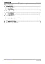
LCD Module User Manual Document Name: HMT035ATA-D Page: 2 of 12
Open the catalog to page 2
LCD Module User Manual 1 Basic Specification TOPWAY HMT035ATA-D is a Smart TFT Module with 32bit MCU on board. Its graphics engine provides numbers of outstanding features. It supports TOPWAY TML for preload and pre-design display interface that simplify the host operation and development time. Suitable for industry control, instrumentation, medical electronics, power electric equipment applications. General Specification Screen Size(Diagonal) : Resolution : Color Depth : Pixel Configuration : Display Mode : Viewing Direction : Outline Dimension : Active Area : Backlight : Command I/F: Project...
Open the catalog to page 3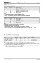
LCD Module User Manual Terminal Function UART Interface Terminal (K1) Pin No. Pin Name I/O 1,2 3 4 5 6 7,8 Descriptions Power supply (6~26) High-Speed UART Reset-To-Send ,Output , High Active High-Speed UART TX Data ,Output High-Speed UART RX Data ,Input High-Speed UART RX Data ,Input Ground, (0V) Note. *1. User data and commands transfer through this terminal. *2. HOST using command hand shake during communication is suggested. USB Interface Terminal (K3) Pin No. Pin Name I/O 1 2 3 4 5 Descriptions Power supply USB DATA negative signal USB DATA positive signal Ground, (0V) Note. *1. TML files...
Open the catalog to page 4
LCD Module User Manual Items Symbol Operating Voltage Vdd Rx Input MARK(1) VRxDM Rx Input SPACE(0) VRxDS Tx Output MARK(1) VTxDM Tx Output SPACE(0) VTxDS RTS(BUSY) Output High VTxDH RTS(BUSY) Output Low VTxDL Operating Current IDD Operating Current (USB) IVUSB Battery Supply Current IBAT Note. *1. Normal display condition GND=0V, TOP =25C Applicable Pin/FUNC VDD Rx Rx Tx Tx RTS(BUSY) RTS(BUSY) VDD (*1) VUSB AC Characteristics Items Start bit Data bit Parity bit Stop bit Baud Rate(*1) Serial Data Flow Control Note. *1.Baud Rate (1200bps~115200bps) could be adjusted by software config. Document...
Open the catalog to page 5
LCD Module User Manual Function Specifications Basic Operation Function Descriptions HMT035ATA-D TML files Picture files ICONS files TFT Display UART interface Custom Memories VP variables Control and Draw Engine TML files, Picture files, ICON files are stored inside FLASH memory area. They are preloaded to HMT035ATA-D for stand alone interface use. Those files are preloaded via USB interface as an USB drive. All the interface flow and the touch response are based on the preloaded TML files VP variables memory is inside RAM area, it provides real time access via UART by the HOST or display onto...
Open the catalog to page 6
LCD Module User Manual Quick Start Guide Install TOPWAY Graphics Editor Import pictures 2. design UI flow Connect to host Show 5. real time data Command Descriptions Please refer to “SMART LCD Command Manual , Protocol V1.00” or later. Document Name: HMT035ATA-D Page: 7 of 1
Open the catalog to page 7
LCD Module User Manual Note:The parameter is slightly changed by temperature, driving voltage and materiel. Document Name: HMT035ATA-D Page: 8 of 12
Open the catalog to page 8
LCD Module User Manual Note 1: The data are measured after LEDs are turned on for 5 minutes. LCM displays full white. The brightness is the average value of 9 measured spots. Measurement equipment PR-705 (Φ8mm) Measuring condition: - Measuring surroundings: Dark room - Measuring temperature: Ta=25℃. - Adjust operating voltage to get optimum contrast at the center of the display. Measured value at the center point of LCD panel after more than 5 minutes while backlight turning on. Note 2: The luminance uniformity is calculated by using following formula. △Bp = Bp (Min.) / Bp (Max.)×100 (%) Bp (Max.)...
Open the catalog to page 9
LCD Module User Manual 6 CTP Application Precautions 6.1 CTP Mounting Precaution 6.1.1 Bezel Mounting (Figure 1) - The bezel window should be bigger than the CTP active area. It should be≥0.5mm each side. - Gasket should be installed between the bezel and the CTP surface. The final gap should be about 0.5~1.0mm. - It is recommended to provide an additional support bracket for backside support when necessary (e.g. slim type TFT module without mounding structure). They should only provide appropriate support and keep the module in place. - The mounting structure should be strong enough to prevent...
Open the catalog to page 10
LCD Module User Manual 6.2.1 The product made of glass. Do not subject it to a mechanical shock by dropping it from a high place, etc. 6.2.2 Do not apply excessive or uneven force to the product since this may damage to the performance. 6.2.3 If the display surface is contaminated, breathe on the surface and gently wipe it with a soft dry cloth. If still not completely clear, moisten cloth with Isopropyl alcohol or Ethyl alcohol solvents. Solvents other than those mentioned above may damage the product. Especially, do not use Water, Ketone, Aromatic solvents. 6.2.4 Do not attempt to disassemble...
Open the catalog to page 11
LCD Module User Manual 7 Precautions of using LCD Modules Please refer to "LCD-Module-Design-Handling-Precaution.pdf". Document Name: HMT035ATA-D Page: 12 of 12
Open the catalog to page 12All TOPWAY LCD catalogs and technical brochures
 TOPWAY Smart LCD SGTools Handbook
108 Pages
 10.1" TFT LCD Module
1 Page
 MONO Product
2 Pages
 LMT050DNCFWU-NNA-2
15 Pages
 LMT080TDGP01
16 Pages
 HKT035BTB-1D
36 Pages
 HMT050AMC-C
17 Pages
 HMT043ATA-6C
31 Pages
 TM035PDHG09
42 Pages
 TM035PDHG03
31 Pages
 TM028HDZP01
28 Pages
 LM256160DCW-1
14 Pages
 LM12896FCW-1
17 Pages
 LM12832KCW
13 Pages
 LM2088EFW-9
12 Pages
 LM3122AGG-2
12 Pages
 LM240160YCW
18 Pages
 LM6093ACW
14 Pages
 HMT104ATA-C
11 Pages
 HMT101ATA-D
36 Pages
 HKT080ATA-C
1 Page
 HMT080ATA
1 Page
 HKT070DTA-1C
11 Pages
 HMT070DTA-D
1 Page
 HKT070DMC-2C
19 Pages
 HMT070ETD-C
31 Pages
 HMT070ETD-1D
34 Pages
 HMT056ATA-C
1 Page
 HMT050CB-1C
31 Pages
 HMT050DTA-D
1 Page
 HKT050ATA-C
1 Page
 HMT043ATA-7C
32 Pages
 HMT043GTA-1D
37 Pages
 HKT043BMC-2C
17 Pages
 HMT043ATA-3C
11 Pages
 HMT043BMC-C
1 Page
 HMT043ATA-4C
11 Pages
 HKT043BMC-C
1 Page
 HKT043ATA-1C
12 Pages
 HMT028ATB-C
12 Pages
 HKT104ATA-C
31 Pages
 HMT068BTA-C
33 Pages
 HMT070ATA-1C
32 Pages
 HMT080ATA-C
33 Pages
 HMT090ATA-C
30 Pages
 HMT101ATA-C
33 Pages
 HMT050ATA-2C
31 Pages
 HMT043ATA-2C
32 Pages
 IC Raio RA6963 LCD Controller
42 Pages
 IC Epson S1D13L01 LCD Controller
118 Pages
 IC EPSON S1D13700 LCD Controller
133 Pages
 EPSON S1D13709 LCD Controller
192 Pages
 Samsung S6B0108 LCD Driver
23 Pages
 Avant SBN0064G LCD Driver
37 Pages
 Avant SBN6400G LCD Driver
34 Pages
 EPSON SED1335 LCD Controller
95 Pages
 SGS-THOMSON ST7282
23 Pages
 Raio RA6963 LCD Controller
42 Pages
 Raio RA8875 TFT LCD Controller
174 Pages
 Raio RA8835 LCD Controller
93 Pages
 RAIO RA8803 LCD Controller
8 Pages
 HMT035ATA-1C
1 Page
 Smart LCD introduction
14 Pages
 Topway company introduction
14 Pages
 TFT module in bezel
1 Page
 Topway TFT LCD
1 Page
 LM12864L Series
1 Page
 LM12864T Series
1 Page
 LM12864F Series
1 Page
 LM6060C Series
1 Page
 LM12864M Series
1 Page
 LM6029A Series
1 Page
 LM6059B Series
1 Page
 LM24048A Series
1 Page
 LM13232A Series
1 Page
 LM160160A Series
1 Page
 LMB402C Series
1 Page
 LMB242A Series
1 Page
 LMB204C Series
1 Page
 LM3121 Series
1 Page
 LMB404A Series
1 Page
 HMT043FC-1C
1 Page
 LM3123 Series
1 Page
 LMB204B Series
1 Page
 LMB202E Series
1 Page
 LMB202D Series
1 Page
 LMB164A Series
1 Page
 LMB162G Series
1 Page
 LMB162H Series
1 Page
 LMB162N Series
1 Page
 LMB162A Series
1 Page
 LMB0820D Series
1 Page
 LMB0820C Series
1 Page
 LMB0820A Series
1 Page
 LMB081N Series
1 Page
 LMB081A Series
1 Page
 LMB162X series
1 Page
 LMT057DNAFWU-AAN series
1 Page
 LMT057DNAFWU-AAA series
1 Page
 LMT104SDH01 Series
1 Page
 TOPWAY Product List (Y2012)
4 Pages
 TFT LCD module
1 Page
 Without controller
1 Page
 Chinese fonts
1 Page
 Built-in controller
1 Page
 Character module
1 Page


- Bourn And Koch touch screen monitor
- Bourn And Koch industrial monitor
- Bourn And Koch LCD display
- Bourn And Koch HDMI monitor
- Bourn And Koch VESA mounting monitor
- Bourn And Koch industrial display
- Bourn And Koch TFT LCD display
- Bourn And Koch IP65 monitor
- Bourn And Koch touch screen display
- Bourn And Koch color display
- LED display panel
- Bourn And Koch high-brightness monitor
- Bourn And Koch TFT monitor
- Bourn And Koch electronic display
- Control display system
- Bourn And Koch wall-mount monitor
- IPS display panel
- Bourn And Koch backlit display
- Programmable display system