- Catalogs
- TOPWAY LCD
- HKT070DTA-1C
- Company
- Products
- Catalogs
- News & Trends
- Exhibitions
HKT070DTA-1C
1 /11Pages

HKT070DTA-1C
1 /11Pages
Catalog excerpts

HKT070DTA-1C LCD Module User Manual Release Date - Preliminary Draft release - Assemble Precaution Document Name: HKT070DTA-1C Page: 1 of 10
Open the catalog to page 1
LCD Module User Manual Document Name: HKT070DTA-1C Page: 2 of 10
Open the catalog to page 2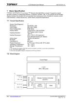
LCD Module User Manual 1 Basic Specification TOPWAY HKT070DTA-1C is a Smart TFT Module with 32bit MCU on board. Its graphics engine provides numbers of outstanding features. It supports TOPWAY TML 3.0 for preload and pre-design display interface that simplify the host operation and development time. Suitable for industry control, instrumentation, medical electronics, power electric equipment applications. General Specification Screen Size(Diagonal) : Resolution : Color Depth : Pixel Configuration : Display Mode : Viewing Direction : Outline Dimension : Active Area : Backlight : Command I/F: Project...
Open the catalog to page 3
LCD Module User Manual Terminal Function RS232 Interface Terminal (K1) Pin No. Pin Name I/O 1 2 3 Descriptions Ground, (0V) No connection, leave open Request To Send (could function as busy BUSY signal) (eg. to PC’s RS232C pin8 <9pin D-connector> ) Data output (eg. to PC’s RS232C pin2 <9pin D-connector>) Data Input (eg. to PC’s RS232C pin3 <9pin D-connector>) Power supply (11.0 ~ 26.0) Note. *1. User data and commands transfer through this terminal. *2. HOST using command hand shake during communication is suggested. USB Interface Terminal (K2) Pin No. Pin Name I/O 1 2 3 4 5 Descriptions Power...
Open the catalog to page 4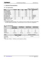
LCD Module User Manual VSS=0V, VDD=12V, TOP =25C Items Symbol MIN. TYP. MAX. Unit Applicable Pin Operating Voltage VDD 11.0 12.0 26.0 V VDD Rx Input MARK(1) VRxM -3.0 -15.0 V Rx Rx Input SPACE(0) VRXS +3.0 +15.0 V Rx Tx Output MARK(1) VTXM -3.0 -15.0 V Tx Tx Output SPACE(0) VTXS +3.0 +15.0 V Tx RTS Output High VTXH -3.0 -15.0 V RTS(BUSY) RTS Output Low VTXL +3.0 +15.0 V RTS(BUSY) Operating Current IDD 315 mA VDD (*1) Operating Current (USB) IVUSB 200 mA VUSB Battery Supply current IBAT 6 uA (*2) Note. *1. Normal display condition. *2. For Battery driving RTC application, RTC configuration should...
Open the catalog to page 5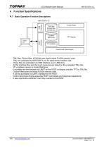
LCD Module User Manual Basic Operation Function Descriptions HKT070DTA-1C TML files Picture files ICONS files UART interface Custom Memories Touch Panel VP variables Control and Draw Engine TML files, Picture files, ICON files are stored inside FLASH memory area. They are preloaded to HKT070DTA-1C for stand alone interface use. Those files are preloaded via USB interface as an USB drive. All the interface flow and the touch response are based on the preloaded TML files VP variables memory is inside RAM area, it provides real time access via UART by the HOST or display onto the TFT by TML file....
Open the catalog to page 6
LCD Module User Manual Quick Start Guide Install TOPWAY Graphics Editor Import pictures 2. design UI flow Connect to host Show 5. real time data Command Descriptions Please refer to “SMART LCD Command Manual” . Document Name: HKT070DTA-1C Page: 7 of 1
Open the catalog to page 7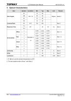
LCD Module User Manual 5 Optical Characteristics Item View Angles Contrast Ratio Response Time TOFF White Blue Uniformity NTSC Luminance 1.IF= 40 mA, and the ambient temperature is 25℃. 2. The test systems refer to Note 1 and Note 2.
Open the catalog to page 8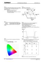
LCD Module User Manual Note 1: The data are measured after LEDs are turned on for 5 minutes. LCM displays full white. The brightness is the average value of 9 measured spots. Measurement equipment SR-3A (1°) Measuring condition: - Measuring surroundings: Dark room - Measuring temperature: Ta=25℃. - Adjust operating voltage to get optimum contrast at the center of the display. Note 3: The definition of contrast ratio (Test LCM using SR-3A (1°)): Luminance When LCD is at “White” state Contrast = Ratio(CR) Luminance When LCD is at “Black” state (Contrast Ratio is measured in optimum common electrode...
Open the catalog to page 9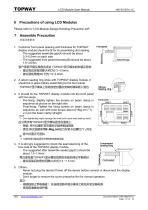
LCD Module User Manual 6 Precautions of using LCD Modules Please refer to "LCD-Module-Design-Handling-Precaution.pdf". Assemble Precaution 安装注意事项 1. Customer front panel opening and thickness for TOPWAY display module should be fit for its assembling and sealing. The suggested assemble gap(A) should be about 0.3~0.5mm on each side. The suggested front panel thickness(B) should be about 1.5~4.0mm. 客户面板开窗及厚度应适合 TOPWAY显示模块的安装及密封. · 建议每边安装间隙(A)约为0.3 ~0.5mm. · 建议面板厚度(B) 约为1.5~4.0mm. 2. A silicon sealing ring ships with TOPWAY display module. It should be in place before assembling to the front...
Open the catalog to page 10All TOPWAY LCD catalogs and technical brochures
 TOPWAY Smart LCD SGTools Handbook
108 Pages
 10.1" TFT LCD Module
1 Page
 MONO Product
2 Pages
 LMT050DNCFWU-NNA-2
15 Pages
 LMT080TDGP01
16 Pages
 HKT035BTB-1D
36 Pages
 HMT050AMC-C
17 Pages
 HMT043ATA-6C
31 Pages
 TM035PDHG09
42 Pages
 TM035PDHG03
31 Pages
 TM028HDZP01
28 Pages
 LM256160DCW-1
14 Pages
 LM12896FCW-1
17 Pages
 LM12832KCW
13 Pages
 LM2088EFW-9
12 Pages
 LM3122AGG-2
12 Pages
 LM240160YCW
18 Pages
 LM6093ACW
14 Pages
 HMT104ATA-C
11 Pages
 HMT101ATA-D
36 Pages
 HKT080ATA-C
1 Page
 HMT080ATA
1 Page
 HMT070DTA-D
1 Page
 HKT070DMC-2C
19 Pages
 HMT070ETD-C
31 Pages
 HMT070ETD-1D
34 Pages
 HMT056ATA-C
1 Page
 HMT050CB-1C
31 Pages
 HMT050DTA-D
1 Page
 HKT050ATA-C
1 Page
 HMT043ATA-7C
32 Pages
 HMT043GTA-1D
37 Pages
 HKT043BMC-2C
17 Pages
 HMT043ATA-3C
11 Pages
 HMT043BMC-C
1 Page
 HMT043ATA-4C
11 Pages
 HKT043BMC-C
1 Page
 HKT043ATA-1C
12 Pages
 HMT035ATA-D
13 Pages
 HMT028ATB-C
12 Pages
 HKT104ATA-C
31 Pages
 HMT068BTA-C
33 Pages
 HMT070ATA-1C
32 Pages
 HMT080ATA-C
33 Pages
 HMT090ATA-C
30 Pages
 HMT101ATA-C
33 Pages
 HMT050ATA-2C
31 Pages
 HMT043ATA-2C
32 Pages
 IC Raio RA6963 LCD Controller
42 Pages
 IC Epson S1D13L01 LCD Controller
118 Pages
 IC EPSON S1D13700 LCD Controller
133 Pages
 EPSON S1D13709 LCD Controller
192 Pages
 Samsung S6B0108 LCD Driver
23 Pages
 Avant SBN0064G LCD Driver
37 Pages
 Avant SBN6400G LCD Driver
34 Pages
 EPSON SED1335 LCD Controller
95 Pages
 SGS-THOMSON ST7282
23 Pages
 Raio RA6963 LCD Controller
42 Pages
 Raio RA8875 TFT LCD Controller
174 Pages
 Raio RA8835 LCD Controller
93 Pages
 RAIO RA8803 LCD Controller
8 Pages
 HMT035ATA-1C
1 Page
 Smart LCD introduction
14 Pages
 Topway company introduction
14 Pages
 TFT module in bezel
1 Page
 Topway TFT LCD
1 Page
 LM12864L Series
1 Page
 LM12864T Series
1 Page
 LM12864F Series
1 Page
 LM6060C Series
1 Page
 LM12864M Series
1 Page
 LM6029A Series
1 Page
 LM6059B Series
1 Page
 LM24048A Series
1 Page
 LM13232A Series
1 Page
 LM160160A Series
1 Page
 LMB402C Series
1 Page
 LMB242A Series
1 Page
 LMB204C Series
1 Page
 LM3121 Series
1 Page
 LMB404A Series
1 Page
 HMT043FC-1C
1 Page
 LM3123 Series
1 Page
 LMB204B Series
1 Page
 LMB202E Series
1 Page
 LMB202D Series
1 Page
 LMB164A Series
1 Page
 LMB162G Series
1 Page
 LMB162H Series
1 Page
 LMB162N Series
1 Page
 LMB162A Series
1 Page
 LMB0820D Series
1 Page
 LMB0820C Series
1 Page
 LMB0820A Series
1 Page
 LMB081N Series
1 Page
 LMB081A Series
1 Page
 LMB162X series
1 Page
 LMT057DNAFWU-AAN series
1 Page
 LMT057DNAFWU-AAA series
1 Page
 LMT104SDH01 Series
1 Page
 TOPWAY Product List (Y2012)
4 Pages
 TFT LCD module
1 Page
 Without controller
1 Page
 Chinese fonts
1 Page
 Built-in controller
1 Page
 Character module
1 Page


- Monitor with touchscreen
- Industrial monitor
- LCD display panel
- HDMI monitor
- VESA mounting monitor
- Industrial display panel
- TFT display module
- IP65 monitor
- Touch screen display panel
- Color display panel
- LED display panel
- High-brightness monitor
- TFT-LCD monitor
- Electronic display panel
- Control display system
- Wall-mount monitor
- IPS display panel
- Backlit display panel
- Programmable display system