
- Catalogs
- Tool-Temp AG
- CLASSIC Duo 90/150 12 E 90/150 12 H

CLASSIC Duo 90/150 12 E 90/150 12 H
CLASSIC Duo 90/150 12 E 90/150 12 H
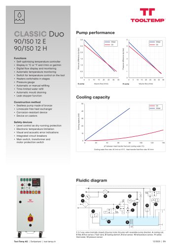
- Self-optimising temperature controller with digital display options in °C/°F and l/min/gal/min.
- Features include automatic temperature monitoring, switchable heaters, pressure gauge, and automatic/manual refilling.
- Additional functionalities include time-limited water refill, automatic mould draining, and a leak stopper function.
- Sealless bronze pump, limescale-free heat exchanger, and corrosion-resistant design.
- Device is mobile with castors for easy movement.
- Includes level control for dry-running protection, electronic temperature limitation, and visual/acoustic error indications.
- Integrated circuit breakers and motor protection switch ensure operational safety.
- Maximum temperature: Water 90°C, Oil 150°C.
- Heating output: Water 12 kW, Oil 6 kW.
- Filling volume: Minimum 16 litres, maximum 20 litres.
- Motor rated power: Type E 0.75 kW, Type H 1.5 kW.
- Control system: MP-888 with FeKo type J temperature sensor.
- Heat transfer fluid connections: ½" BSPP female thread.
- Cooling water inlet/outlet: ⅜" BSPP threads with water filter.
- Operating temperature range: 5–40°C, relative humidity 40–80% RH.
- Installation requires at least 10 cm clearance for ventilation.
- Sound pressure level is below 70 dB (A).
- Voltage options: 380-415 V, 50 Hz/440-480 V, 60 Hz/380 V, 60 Hz/200-230 V, 50 Hz/200-240 V, 60 Hz.
- Connected load: Pump type E 12.9 kW, Pump type H 13.6 kW.
- Protection class: IP44, CE labeled.
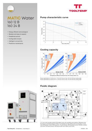
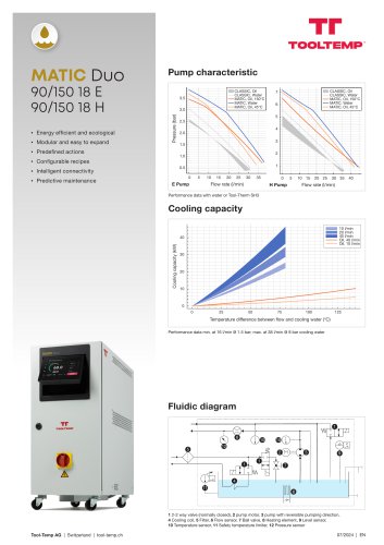
- Diagrams illustrate the relationship between volume flow and pressure difference for water and oil, as well as cooling capacity relative to temperature differences.
Catalog excerpts
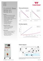
Construction method ▪ Sealless pump made of bronze ▪ Limescale-free heat exchanger ▪ Corrosion-resistant device ▪ Device on castors Safety devices ▪ Level control as dry-running protection ▪ Electronic temperature limitation ▪ Visual and acoustic error indications ▪ Integrated circuit breakers ▪ Main switch, transformer and motor protection switch Functions ▪ Self-optimising temperature controller ▪ Display in °C or °F and l/min or gal/min ▪ Digital flow display and monitoring ▪ Automatic temperature monitoring ▪ Switch for temperature control on the tool ▪ Heaters switchable in stages ▪ Pressure gauge ▪ Automatic or manual refilling ▪ Time-limited water refill ▪ Automatic mould draining ▪ Leak stopper function Pump performance Volume flow (l/min) Volume flow (l/min) ΔT between Heat transfer fluid and cooling water (°C) Cooling water flow rate: 40 l/min at 10°C · Heat transfer fluid flow rate: 30 l/min Fluidic diagram CLASSIC 1 2-2 way valve (normally closed), 2 pump motor, 3 pump with reversible pump direction, 4 cooling coil, 5 filter, 6 flow sensor, 7 ball valve, 8 heating element, 9 level sensor, 10 temperature sensor, 11 safety thermostat, 12 pressure sensor
Open the catalog to page 1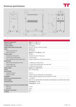
Maximum temperature Heating output Cooling capacity Filling volume (heat transfer fluid) Pressure and flow rate Motor rated power Control system Temperature measurement Pump-pressure measurement Flow measurement (heat-transfer fluid) Connections Heat transfer fluid (feed and return) Cooling water inlet Cooling water outlet Empty weight Colour Temperature range Relative humidity Continuous sound pressure level Power supply Connected load Conductor cross-section of connection cable 200-240 V 380-480 V Protection class device Labeling Water 90 °C, Oil 150 °C Water 12 kW, Oil 6 kW See diagram Minimum...
Open the catalog to page 2All Tool-Temp AG catalogs and technical brochures
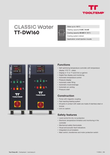 CLASSIC Water TT-DW160
2 Pages
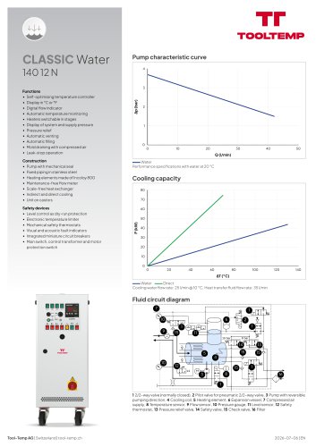 CLASSIC Water 140 12 N
2 Pages
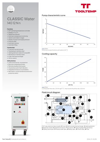 CLASSIC Water 140 12 N n
2 Pages
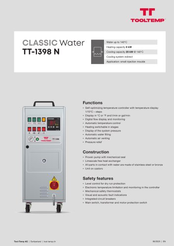 CLASSIC Water TT-1398 N
2 Pages
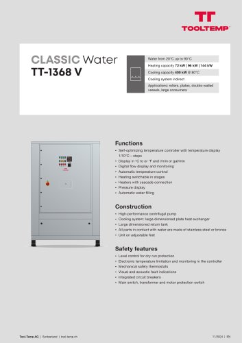 CLASSIC Water TT-1368 V
2 Pages
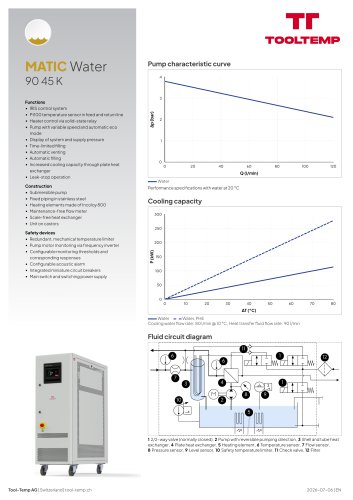 MATIC Water 90 45 K
2 Pages
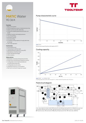 MATIC Water 90 36 K
2 Pages
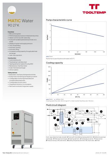 MATIC Water 90 27 K
2 Pages
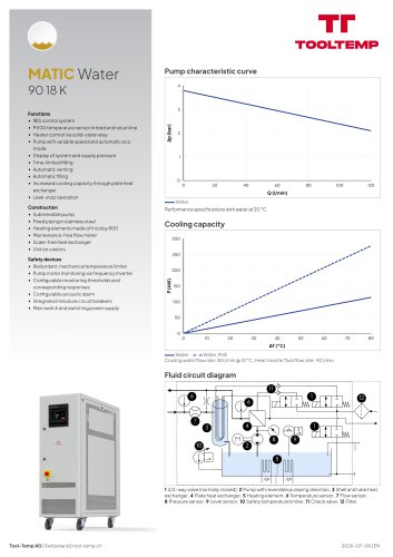 MATIC Water 90 18 K
2 Pages
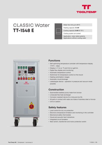 CLASSIC Water TT-1548 E
2 Pages
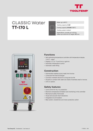 CLASSIC Water TT-170 L
2 Pages
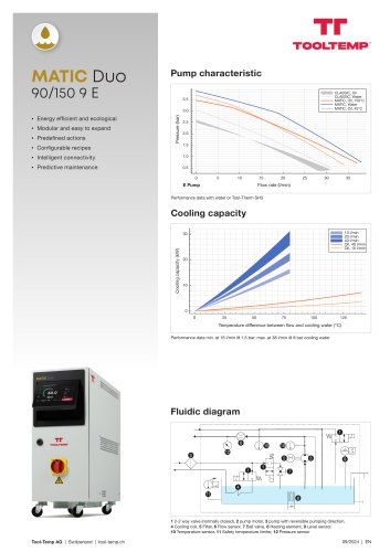 MATIC Duo 90/150 9 E
2 Pages
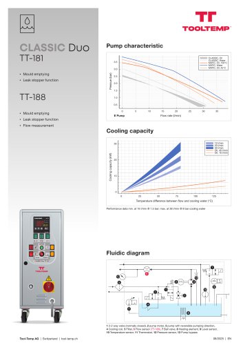 CLASSIC Duo TT-181
2 Pages
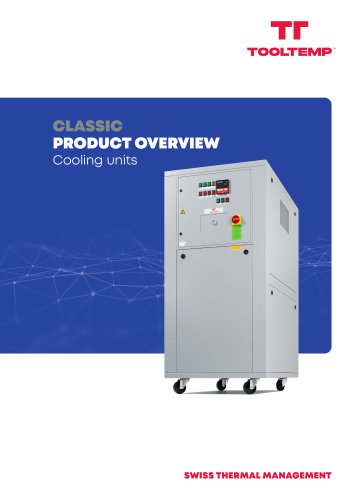 Product overview CU
11 Pages
 Company Portrait
15 Pages
- Tool-Temp digital temperature control
- Tool-Temp digital temperature control unit
- Tool-Temp fluid circulation temperature control unit
- Tool-Temp compact temperature control
- Tool-Temp cooling temperature control unit
- Tool-Temp heating temperature control unit
- Tool-Temp water temperature control unit
- Tool-Temp automatic temperature control unit
- Tool-Temp process temperature control unit
- Tool-Temp oil temperature control unit
- Tool-Temp plastic moulding temperature control unit
- Tool-Temp industrial temperature control unit
- Tool-Temp automation temperature control unit
- Tool-Temp mobile temperature control unit
- Tool-Temp temperature control unit with touchscreen
- Tool-Temp safety temperature control unit
- Tool-Temp IP54 temperature control unit
- Tool-Temp compact temperature control unit
- Tool-Temp pressurized water temperature control unit