- Catalogs
- Tolomatic, TOL-O-MATIC
- MXE Electric Rodless Actuator Catalog
MXE Electric Rodless Actuator Catalog
1 /56Pages

MXE Electric Rodless Actuator Catalog
1 /56Pages
Catalog excerpts

MXE SCREW DRIVE ACTUATORS S SOLID BEARING P PROFILED RAIL LINEAR SOLUTIONS MADE EASY LINEAR SOLUTIONS MADE EASY
Open the catalog to page 1
THE MXE ELECTRIC ACTUATOR – DESIGNED TO OUTLAST EVERY RODLESS ACTUATOR ON THE MARKET The MXE electric actuator is exactly what you expect from the industry’s number one rodless supplier. Designed with our exclusive ENDURANCE TECHNOLOGYSM features, the MX delivers superior performance to meet the most demanding applications. Nobody knows rodless like Tolomatic, and the MX proves it. • DURABLE BEARINGS. Two bearing choices to match your application needs. Solid bearing design optimizes stress distribution for optimal performance. Profiled rail design uses recirculating ball technology to reduce...
Open the catalog to page 2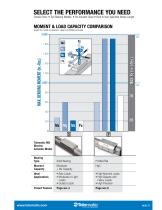
CONTENTS SELECT THE PERFORMANCE YOU NEED NEED SELECT THE PERFORMANCE YOU MOMENTMOMENT CAPACITY COMPARISON & LOAD & LOAD CAPACITY COMPARISON Graph for data comparison, data from Graph for model comparison,model from MXE40 actuator MXE40 actuator MAX. BENDING MOMENT (in.-lbs.) MAX. BENDING MOMENT (in.-lbs.) Bearing Type Solid Bearing Solid Bearing Tolomatic MX Tolomatic MX Electric Electric Actuator Model Actuator Model Bearing Type S Reverse Parallel Motor Mounting Profiled Rail Moment Moment Moderate High Moderate High Capacity Capacity Capacity Mx Capacity + Mx + Ideal Ideal • Side Loads • Side...
Open the catalog to page 3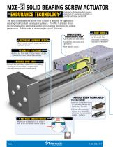
MXE-S SOLID BEARING SCREW ACTUATOR Endurance Technology features are designed for maximum durability to provide extended service life. The MXE-S rodless electric screw-drive actuator is designed for applications requiring moderate load carrying and guidance. The MXE-S actuator utilizes two field replaceable solid bearings that optimize stress distribution for optimal performance. Built-to-order in stroke lengths up to 178 inches. LARGE FLEXIBLE MOUNTING PATTERN LIGHTWEIGHT ALUMINUM DESIGN •Clear anodized extrusion design is optimized for rigidity and strength • Carrier gives more load stability...
Open the catalog to page 4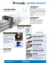
… MAXIMUM DURABILITY YOUR MOTOR HERE YOU CAN CHOOSE: •Motor or gearbox supplied and installed by Tolomatic • Specify the device to be installed and actuator ships with proper mounting hardware - MXE is a “Your Motor Here” actuator for easy in-line motor installation. Check our website (www.tolomatic.com/ymh) for complete YMH information • Specify and ship your device to Tolomatic for factory installation INCH OR METRIC MOUNTING • Your choice of inch (US standard) or metric mounting to the carrier MOTOR ORIENTATION YOU CAN CHOOSE: •In-line option directly couples the driving shaft and is a one-piece...
Open the catalog to page 5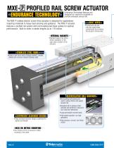
MXE-P PROFILED RAIL SCREW ACTUATOR Endurance Technology features are designed for maximum durability to provide extended service life. The MXE-P rodless electric screw-drive actuator is designed for applications requiring moderate to heavy load carrying and guidance. The MXE-P actuator features a profiled rail system with recirculating ball linear guides for optimal performance. Built-to-order in stroke lengths up to 178 inches. DUST WIPER • Formed end cap and side dust wipers keep contaminants from entering the actuator’s internal area INTERNAL MAGNETS •Standard feature that allows sensor installation...
Open the catalog to page 6
… MAXIMUM DURABILITY YOUR MOTOR HERE YOU CAN CHOOSE: •Motor or gearbox supplied and installed by Tolomatic • Specify the device to be installed and actuator ships with proper mounting hardware - MXE is a “Your Motor Here” actuator for easy in-line motor installation. Check our website (www.tolomatic.com/ ymh) for complete information • Specify and ship your device to Tolomatic for factory installation • Reduces overall actuator envelope • Large mounting pattern for excellent load stability MOTOR ORIENTATION YOU CAN CHOOSE: •In-line option directly couples the driving shaft and is a one-piece...
Open the catalog to page 7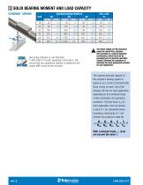
S SOLID BEARING MOMENT AND LOAD CAPACITY STANDARD CARRIER MAXIMUM BENDING MOMENTS My Mz N-m in-lbs N-m in-lbs N-m 2.5 19 2.1 25 2.8 Use sizing software or call Tolomatic (1-800-328-2174) with application information. We will provide any assistance needed to determine the proper MXE screw-driven actuator. The above ratings are the maximum values for shock-free, vibrationfree operation in a typical industrial environment, which must not be exceeded even in dynamic operation. Contact Tolomatic for assistance in selecting the most appropriate actuator for your application. The moment and load capacity...
Open the catalog to page 8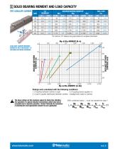
S SOLID BEARING MOMENT AND LOAD CAPACITY 452 “D” 200 (inches) DISTANCE BETWEEN CARRIERS 22.6 1,050 *At minimum “D” distance see graph below for complete information MAXIMUM BENDING MOMENTS* Mxa Mya Mza 226 2,000 in-lbs N-m in-lbs N-m in-lbs N-m 44 5.0 175 19.8 175 19.8 AUXILIARY CARRIER BENDING MOMENTS WITH INCREASED “D” DISTANCE BETWEEN CARRIERS DISTANCE BETWEEN CARRIERS (mm) DISTANCE BETWEEN CARRIERS (in) Ratings were calculated with the following conditions: 1.) Coupling between carriers is rigid. 3.) Coupling device applies no 2.) Load is equally distributed between carriers. misalignment...
Open the catalog to page 9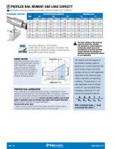
P PROFILED RAIL MOMENT AND LOAD CAPACITY Mating surface of mounted component must maintain a flatness of at least .0015" [0.040 mm] STANDARD CARRIER MAXIMUM BENDING MOMENTS Mx My Mz in-lbs N-m in-lbs N-m in-lbs N-m 39 4.5 339 38.3 339 38.3 Use sizing software or call Tolomatic (1-800-328-2174) with application information. We will provide any assistance needed to determine the proper MXE screw-driven actuator. SPEED FACTOR LINEAR SPEED (mm/sec) 1.50 SPEED FACTOR SPEED FACTOR FOR APPLICATIONS WITH HIGH SPEED OR SIGNIFICANT SHOCK AND VIBRATION: Calculated values of loads and bending moments must...
Open the catalog to page 10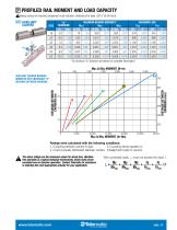
P PROFILED RAIL MOMENT AND LOAD CAPACITY 452 Mating surface of mounted component must maintain a flatness of at least .0015" [0.040 mm] z M DC AUXILIARY CARRIER “D” (inches) DISTANCE BETWEEN CARRIERS “D” (inches) DISTANCE BETWEEN CARRIERS 6.0 152 “D” (inches) DISTANCE BETWEEN CARRIERS *At minimum “D” distance see below for complete information AUXILIARY CARRIER BENDING MOMENTS WITH INCREASED “D” DISTANCE BETWEEN CARRIERS DISTANCE BETWEEN CARRIERS (in) DISTANCE BETWEEN CARRIERS (mm) Ratings were calculated with the following conditions: 1.) Coupling between carriers is rigid. 3.) Coupling device...
Open the catalog to page 11All Tolomatic, TOL-O-MATIC catalogs and technical brochures
 CSWX Compact ServowWeld Actuator
12 Pages
 FOOD & BEVERAGE SOLUTIONS
8 Pages
 MAG COUPLED CYLINDER
20 Pages
 TKS & TKB ACTUATORS
32 Pages
 MXE SCREW DRIVE ACTUATORS
52 Pages
 210 SERIES BRAKES
12 Pages
 Engineering Resources
23 Pages
 Electric Actuator
4 Pages
 BCS Rodless Screw Drive Actuator
28 Pages
 ERD Catalog
32 Pages
 Cable Cylinder Catalog
40 Pages
 Brake Intensifier Brochure
2 Pages
 BC2 Pneumatic Band Cylinder
27 Pages
 ServoWeld System
20 Pages
 ACS Drive Controller
12 Pages
 ERD Electric Rod-style Actuator
28 Pages
 MXB Belt Drive Actuator Catalog
24 Pages
 AppTip_SRG
2 Pages
 AppTip_Shocks
2 Pages
 ERD Low-cost Electric Cylinders
28 Pages
 IMA Electric Servo Actuator
24 Pages
 MXE Electric Rodless Actuator
56 Pages


Archived catalogs
 Tolomatic Electric Actuators
36 Pages
 NEW! Electric Stepper Products
16 Pages

- Cylinder
- Lumibird linear actuator
- Positioning table
- Double-acting cylinder
- Translation stage
- Right angle gearhead
- Compact gearhead
- Pneumatic cylinder
- Lumibird gear train gear reducer
- Motorized positioning table
- Lumibird compact actuator
- Friction brake
- Shaft gearhead
- Single-acting cylinder
- Helical gear gearhead
- Compact cylinder
- Standard cylinder