- Catalogs
- Tolomatic, TOL-O-MATIC
- Engineering Resources
Engineering Resources
1 /23Pages

Engineering Resources
1 /23Pages
Catalog excerpts

Engineering Resources LINEAR SOLUTIONS MADE EASY LINEAR SOLUTIONS MADE EASY
Open the catalog to page 1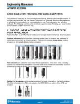
Engineering Resourses Actuator Selection BASIC SELECTION PROCESS AND SIZING EQUATIONS The process of selecting an sizing an electromechanical linear actuator can be complex. It is highly recommended that you contact Tolomatic or a Tolomatic distributor for assistance in selecting the best actuator for your application or use Tolomatic sizing and selection software. The following overview only considers a general case of loading and linear motion and should be used for reference only. 1. CHOOSE LINEAR ACTUATOR TYPE THAT IS BEST FOR YOUR APPLICATION Tolomatic offers several families of rodless...
Open the catalog to page 2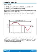
Engineering Resourses Motion Profiles 2. ESTABLISH YOUR MOTION PROFILE AND CALCULATE ACCELERATION/DECELERATION RATES Actuator selection begins with the calculation of speed requirements. A move profile is a plot of velocity vs. time for one full actuator cycle. Each actuator will have a maximum value of linear velocity that it can achieve for each specific load capacity. This maximum value will determine which type of motion profile can be used to complete the move. Two common types of move profiles are triangular and trapezoidal. The figure above provides an example of an actuator working cycle....
Open the catalog to page 3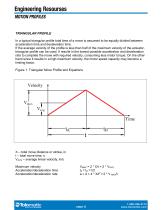
Engineering Resourses Motion Profiles TRIANGULAR PROFILE In a typical triangular profile total time of a move is assumed to be equally divided between acceleration time and deceleration time. If the average velocity of the profile is less than half of the maximum velocity of the actuator, triangular profile can be used. It results in the lowest possible acceleration and deceleration rate to complete the move with required velocity, consuming less motor torque. On the other hand since it results in a high maximum velocity, the motor speed capacity may become a limiting factor. Figure 1. Triangular...
Open the catalog to page 4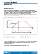
Engineering Resourses Motion Profiles TRAPEZOIDAL PROFILE In addition to acceleration and deceleration time, trapezoidal profile includes a constant speed time. If we assume that acceleration, deceleration and constant speed time are equal, the trapezoidal profile will result in 25% lower maximum linear velocity and 12.5% higher acceleration and deceleration rates, providing a good compromise between acceleration/deceleration rate and maximum velocity. Trapezoidal profile is usually a better choice and the recommended move profile. Figure 2. Trapezoidal Move Profile and Equations Maximum velocity...
Open the catalog to page 5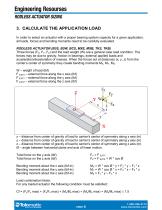
Engineering Resourses RODLESS ACTUATOR SIZING 3. CALCULATE THE APPLICATION LOAD In order to select an actuator with a proper bearing system capacity for a given application, all loads, forces and bending moments need to be carefully evaluated. RODLESS ACTUATOR (B3S, B3W, BCS, MXE, MXB, TKS, TKB) Three forces (FX, FY, FZ) and the load weight (W) are a general case load condition. The forces may be due to gravity, friction in bearings, external applied loads and acceleration/deceleration of masses. When the forces act at distances (x, y, z) from the carrier’s center of symmetry they create bending...
Open the catalog to page 6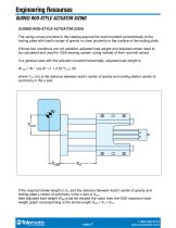
Engineering Resourses Guided Rod-Style Actuator Sizing GUIDED ROD-STYLE ACTUATOR (GSA) The sizing curves provided in the catalog assume the load mounted symmetrically to the tooling plate with load’s center of gravity in close proximity to the surface of the tooling plate. If those two conditions are not satisfied, adjusted load weight and adjusted stroke need to be calculated and used for GSA bearing system sizing instead of their nominal values. In a general case with the actuator mounted horizontally, adjusted load weight is: W adj = W * cos Ø * (1 + 0.53*Ycm), lbf, where Ycm (in) is the distance...
Open the catalog to page 7
Engineering Resourses ACTUATOR SIZING 4. SELECT THE BEARING SYSTEM AND SIZE RODLESS ACTUATORS (B3S, B3W, BCS, MXE, MXB, TKS, TKB) Depending on the nature and type of loading conditions, the application may benefit from using one or the other type of bearing system. B3S, B3W (3 sizes) – heavy duty recirculating ball bearings; BCS (3 sizes) – self lubtricating composite bearings; MXE, MXB (6 sizes) – self lubtricating composite bearings or LM guides providing high rigidity TKS,TKB (4 sizes) – LM guides providing high straightness and flatness of motion Calculated forces and moments must not exceed...
Open the catalog to page 8
Engineering Resourses Actuator Sizing 6. VERIFY THE CRITICAL SPEED OF THE SCREW Verify that application’s peak velocity does not reach the level of the screw’s natural frequency excitation. RPM CR = 4,760,000 * DROOT * f0 / (LB2), where DROOT – screw’s root diameter, in LB – length of screw between bearing supports, in f0 - screw’s end fixity factor (f0 = 1 for rodless actuators (B3S, BCS, MXE, TKS), f0 = 0.8 for rod actuators with nut, supported by internal bearings (RSA, ICR), f0 = 0.36 for rod actuators with unsupported nut (GSA,ERD). Tolomatic catalog graphs provide screw critical speed limits...
Open the catalog to page 9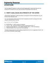
Engineering Resourses Actuator Sizing Use the catalog PV graphs to make sure that the application’s velocity and thrust do not exceed the PV limits for the size, type and lead of the selected Acme lead nut. 8. VERIFY AXIAL BUCKLING STRENGTH OF THE SCREW Verify that the application’s peak thrust does not exceed the critical buckling force (FCR) for the size of the selected screw You can calculate the critical axial force that if exceeded will lead to buckling of the screw using the classical Euler’s formula: FCR = π2 * E * I / (f1 * LN)2, where E = 29,000,000 psi – steel’s modulus of elasticity,...
Open the catalog to page 10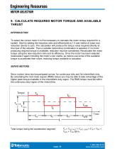
Engineering Resourses Motor Selection 9. CALCULATE REQUIRED MOTOR TORQUE AND AVAILABLE THRUST INTRODUCTION To select the correct motor it is first necessary to calculate the motor torque required for a system. Start by setting the reduction ratio and efficiencies to 1.0 and inertia of motor and reduction device to zero. The calculation will produce the torque value required directly at the input of the actuator. Then a suitable motor/drive combination is selected. If no motor producing required torque is available, reduction must be considered. Recalculate the motor torque using the new reduction...
Open the catalog to page 11All Tolomatic, TOL-O-MATIC catalogs and technical brochures
 CSWX Compact ServowWeld Actuator
12 Pages
 FOOD & BEVERAGE SOLUTIONS
8 Pages
 MAG COUPLED CYLINDER
20 Pages
 TKS & TKB ACTUATORS
32 Pages
 MXE SCREW DRIVE ACTUATORS
52 Pages
 210 SERIES BRAKES
12 Pages
 Electric Actuator
4 Pages
 BCS Rodless Screw Drive Actuator
28 Pages
 ERD Catalog
32 Pages
 Cable Cylinder Catalog
40 Pages
 Brake Intensifier Brochure
2 Pages
 BC2 Pneumatic Band Cylinder
27 Pages
 ServoWeld System
20 Pages
 ACS Drive Controller
12 Pages
 ERD Electric Rod-style Actuator
28 Pages
 MXB Belt Drive Actuator Catalog
24 Pages
 AppTip_SRG
2 Pages
 AppTip_Shocks
2 Pages
 ERD Low-cost Electric Cylinders
28 Pages
 IMA Electric Servo Actuator
24 Pages
 MXE Electric Rodless Actuator
56 Pages


Archived catalogs
 Tolomatic Electric Actuators
36 Pages
 NEW! Electric Stepper Products
16 Pages

- Cylinder
- Electric actuator
- Positioning table
- Double-acting cylinder
- Translation stage
- Right angle gearhead
- Compact gearhead
- Pneumatic cylinder
- Gear train gear reducer
- Motorized positioning table
- Friction brake
- Compact actuator
- Screw actuator
- Shaft gearhead
- Single-acting cylinder
- Helical gear gearhead
- Compact cylinder
- Standard cylinder