
- Catalogs
- Tolomatic, TOL-O-MATIC
- B3S & B3W ELECTRIC RODLESS ACTUATORS


B3S & B3W ELECTRIC RODLESS ACTUATORS

B3S & B3W ELECTRIC RODLESS ACTUATORS
- B3S Screw-Drive Actuator: Offers thrust up to 12 kN (2,700 lbf) and speeds up to 1.5 m/sec (60 in/sec) with stroke lengths up to 4.5 m (179 inches). It uses solid and ball screw/nut types.
- B3W Belt-Drive Actuator: Capable of speeds up to 5.1 m/sec (200 in/sec) with stroke lengths up to 5.3 m (207 inches). It features multiple belt technologies for enhanced performance.
Catalog excerpts

oENDURANCE TECHNOLOGY
Open the catalog to page 1
Tolomatic B3S & B3W Electric Rodless Actuators The Power to Move Heavy Loads The B3S and B3W electric rodless actuators have very large moment and load carrying capacities. The sealed recirculating ball bearing design makes it an excellent choice for challenging environments. For even higher capacity (loads up to 3,629 kg.) choose the Dual 180° Carrier and add an auxiliary carrier. Both actuators utilize a patented internal re-circulating ball bearing guidance system that provides extremely long life. These actuators are capable of carrying loads up to 3,629 kg [8,000 lbs]. A COMPARISON OF SCREW...
Open the catalog to page 2
Applying, Dispensing • Test Fixtures Storage & Retrieval • Pick & Place • Parts Transfer •Laser marking •Material cutting •Adhesive dispensing High Speed Flying Cut Off •Test stations •Product handling •Camera positioning 1-800-328-21
Open the catalog to page 3
B3S RODLESS SCREW DRIVE ACTUATOR Endurance Technology features are designed for maximum durability to provide extended service life. The B3S rodless screw-drive electric actuator is designed for carrying moderate to heavy loads with large bending moment capacity. The B3S utilizes an integral recirculating ball bearing guidance system that provides durable performance and extremely long life. Choose from multiple screw technologies for thrust up 12 kN [2,700 lbf]. Built-to-order in stroke lengths up to 4.5 m [179 inches]. LOAD-BEARING CARRIER DESIGN • Load and moments are transmitted directly...
Open the catalog to page 4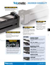
… MAXIMUM DURABILITY SCREW SUPPORT BEARINGS • Unique high thrust bearing assembly design eliminates runout and isolates the linear forces from the drive shaft YOUR MOTOR HERE LIGHTWEIGHT ALUMINUM DESIGN • Black anodized extrusion design is optimized for rigidity and strength • External switch channels on both sides allow easy placement and adjustment of position indicating switches • Inline option directly couples the driving shaft and is typically a one-piece housing construction for optimum alignment and support of the motor • Reverse-parallel option minimizes the overall length and offers...
Open the catalog to page 5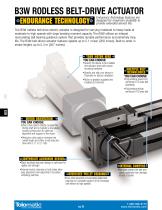
B3W RODLESS BELT-DRIVE ACTUATOR Endurance Technology features are designed for maximum durability to provide extended service life. The B3W rodless belt-drive electric actuator is designed for carrying moderate to heavy loads at moderate to high speeds with large bending moment capacity. The B3W utilizes an integral recirculating ball bearing guidance system that provides durable performance and extremely long life. The B3W belt-driven actuator features speeds up to 5.1 m/sec [200 in/sec]. Built-to-order in stroke lengths up to 5.3 m [207 inches]. YOUR MOTOR HERE • Specify the device to be installed...
Open the catalog to page 6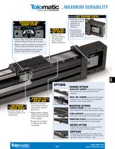
… MAXIMUM DURABILITY BELT TENSIONING SYSTEM RECIRCULATING BALL BEARING SYSTEM FORMED END CAP WIPERS • Unique design incorporates hardened steel raceways integral to the aluminum extrusion • Bearing surfaces are adjusted at the factory for optimum preload and smooth performance • Recirculating ball bearing system provides guidance, high efficiency and durability •Prevent contam inants from entering the sealing band area to protect internal components • Full access to the idle pulley allows ease of adjustment for alignment and tensioning • Dual adjustment screws and field tensioning kit provide...
Open the catalog to page 7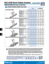
DYNAMIC BENDING MOMENTS AND LOADS A The Dual 180° carrier requires its own proprietary tube supports and foot mounts. See dimensional information. Breakaway torque will also increase when using the Auxiliary carrier or the Dual 180° carrier options. When ordering, determine working stroke and enter this value into the configuration string. Overall actuator length will automatically be calculated. Deflection Considerations: In applications where substantial Mx or My moments come into play, deflection of the cylinder tube, carrier and supports must be considered. The deflection factors shown in...
Open the catalog to page 8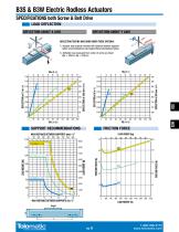
B3S & B3W Electric Rodless Actuators SPECIFICATIONS both Screw & Belt Drive LOAD DEFLECTION DEFLECTION ABOUT X AXIS DEFLECTION ABOUT Y AXIS DEFLECTION TESTING WAS DONE UNDER THESE CRITERIA: 1.) Actuator was properly mounted with distance between supports within recommendations (see Support Recommendations below) 2.) Deflection was measured from center of carrier as shown (Mx = 330mm, My = 203mm) MAXIMUM LOAD MAXIMUM LOAD MAXIMUM LOAD FRICTION FORCE MAX DISTANCE BETWEEN SUPPORTS (mm) “L” 100 MAX DISTANCE BETWEEN SUPPORTS (in) “L”
Open the catalog to page 9
B3S & B3W Electric Rodless Actuators sizeit.tolomatic.com for fast, accurate actuator selection ACTUATOR SIZING SPECIFICATIONS both Screw & Belt Drive AUXILIARY CARRIER: BENDING MOMENT AT ‘D’ DISTANCE DIMENSION “D”* (mm) 100 AUXILIARY DUAL 180˚ CARRIER: BENDING MOMENT AT ‘D’ DISTANCE 100 MOMENT lb-in (in thousands) DIMENSION “D”* (in) Rates shown on both graphs were calculated with these assumptions: 1.) Coupling between carriers is rigid. 2.) Load is equally distributed between carriers. 3.) Coupling device applies no misalignment loads to carriers. * Customer must specify Dimension "D" (Distance...
Open the catalog to page 10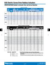
SPECIFICATIONS Related to Actuator Size and Screw Selection METRIC LEAD SCREWS DESCRIPTION Solid Nut Anti-backlash Solid Nut Ball Nut Low-Backlash Ball Nut Contact Tolomatic for higher accuracy and lower backlash options. * For Acme screws, maximum thrust is the maximum continuous dynamic thrust subject to Thrust x Velocity limitation. For ball screws, maximum thrust reflects 90% reliability for 25 million linear millimeters of travel.
Open the catalog to page 11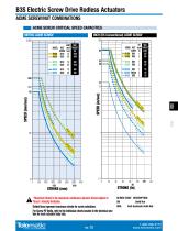
B3S Electric Screw Drive Rodless Actuators ACME SCREW/NUT COMBINATIONS ACME SCREW CRITICAL SPEED CAPACITIES METRIC ACME SCREW INCH (US Conventional) ACME SCREW 100 TPI MAX MODEL NUT/ (turns/ THRUST* SCREW in) (LBS) B3S20 SN01 1 300 B3S20 SN02 2 300 LEAD MAX (mm/ THRUST* turn) (N) 12 1400 25 1400 SPEED (in/sec) SPEED (mm/sec) SCREW CODE DESCRIPTION * Maximum thrust is the maximum continuous dynamic thrust subject to Thrust x Velocity limitation. SN Solid Nut SNA Anti-backlash Solid Nut Dotted lines represent maximum stroke for screw selections. For Screw PV limits, refer to the individual charts...
Open the catalog to page 13All Tolomatic, TOL-O-MATIC catalogs and technical brochures
 CSWX Compact ServowWeld Actuator
12 Pages
 FOOD & BEVERAGE SOLUTIONS
8 Pages
 MAG COUPLED CYLINDER
20 Pages
 TKS & TKB ACTUATORS
32 Pages
 MXE SCREW DRIVE ACTUATORS
52 Pages
 210 SERIES BRAKES
12 Pages
 Engineering Resources
23 Pages
 Electric Actuator
4 Pages
 BCS Rodless Screw Drive Actuator
28 Pages
 ERD Catalog
32 Pages
 Cable Cylinder Catalog
40 Pages
 Brake Intensifier Brochure
2 Pages
 BC2 Pneumatic Band Cylinder
27 Pages
 ServoWeld System
20 Pages
 ACS Drive Controller
12 Pages
 ERD Electric Rod-style Actuator
28 Pages
 MXB Belt Drive Actuator Catalog
24 Pages
 AppTip_SRG
2 Pages
 AppTip_Shocks
2 Pages
 ERD Low-cost Electric Cylinders
28 Pages
 IMA Electric Servo Actuator
24 Pages
 MXE Electric Rodless Actuator
56 Pages


Archived catalogs
 Tolomatic Electric Actuators
36 Pages
 NEW! Electric Stepper Products
16 Pages

- Linear actuator
- Positioning table
- Double-acting cylinder
- Translation stage
- Right angle gearhead
- Compact gearhead
- Pneumatic cylinder
- Gear train gear reducer
- Motorized positioning table
- Friction brake
- Compact actuator
- Screw actuator
- Shaft gearhead
- Single-acting cylinder
- Helical gear gearhead
- Technology positioning stage
- Compact cylinder