TL17
1 /9Pages

TL17
1 /9Pages
Catalog excerpts

Product Segments • Care Motion • Comfort Motion • Ergo Motion • Industrial Motion TiMOTION’s TL17 series electric lifting columns are designed for any height adjustable workstation applications, such as the medical bed for healthcare industry. Constructed with an extruded aluminum rectangular appearance, our TL17 lift column provides a high degree of stability. This column makes engineering and design processes easier and the system safer by replacing older style lifting mechanisms that have many moving parts and pinch points. The 3 stage, telescopic design provides a greatly reduced retracted height and an increased stroke length. General Features Max. load Max. dynamic bending moment 250Nm Max. static bending moment Retracted length Dimension of outer tube Hall sensor(s) Silver, black Operational temperature range
Open the catalog to page 1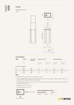
Standard Dimensions Retracted Length Load and Speed CODE Self Locking Force (N) Typical Current (A) With Load 24V DC Note 1 Please refer to the approved drawing for the final authentic value. 2 The current & speed in table are tested with 24V DC motor. With a 12V DC motor, the current is approximately twice the current measured in 24V DC; speed will be similar for both voltages. 3 This self-locking force level is reached only when a short circuit is applied on the terminals of the motor. All the TiMOTION control boxes have this feature built-in. 4 Bending moment Y direction = X*0.8 5 Static...
Open the catalog to page 2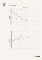
Motor Speed (2800RPM) Speed vs. Load Performance Data (24V DC Motor)
Open the catalog to page 3
TL17 Ordering Key - Front End Socket TL17 Minimum retract length needs to ≥ (stroke / 2) + 150 Cable Exit See page 8 Special Functions for Spindle SubAssembly Functions for Limit Switches See page 8 1 = Two switches at full retracted / extended positions to cut current 3 = Two switches at full retracted / extended positions to send signal Output Signals 0 = Without (the corresponding extension cable TEC needs to be ordered separately) Tubes Direction See page 9 Grounding Function Note 1 TL17 is designed especially for push applications, not suitable for pull applications.
Open the catalog to page 4
TL17 Ordering Key - Side Cable TL17 Cable Exit See page 8 2 = ottom side cable B Special Functions for Spindle SubAssembly Functions for Limit Switches See page 8 1 = Two switches at full retracted / extended positions to cut current 3 = Two switches at full retracted / extended positions to send signal Output Signals 1 = Black (Black cable set) 2 = Matte silver (428C color cable set) Tubes Direction See page 9 Grounding Function 3 = Matte silver (Black cable set) Note 1 TL17 is designed especially for push applications, not suitable for pull applications.
Open the catalog to page 5
Cable Exit See page 8 B = op side - for TH; Bottom side- for TP T C = Bottom side - Y cable, for TH + TP D = Top side - for the 2nd column; Bottom side - for TH & TP; direct cut operation with 2 columns E = Top side - for the 2nd column & TH; Bottom side - for TP; direct cut operation with 2 columns Special Functions for Spindle SubAssembly Functions for Limit Switches See page 8 1 = Two switches at full retracted / extended positions to cut current Output Signals C = Direct cut, water proof, anti-pull Cable Length (mm) See page 9 B = Cable exit #B, L2=L3=100 C = Cable exit #C, L1=L2=L3=100 D...
Open the catalog to page 6
TL17 Ordering Key Appendix Retracted Length (mm) 1. Retracted length needs to ≥ A+B A. Load (N) Note 1 Different retracted length is relative to different bending moment, See page 2 Bottom Top Side Side Cable Cable
Open the catalog to page 7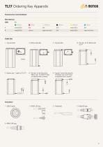
TL17 Ordering Key Appendix Functions for Limit Switches Wire Definitions CODE extend (VDC+) retract (VDC+) extend (VDC+) upper limit switch retract (VDC+) lower limit switch Cable Exit 1 = op end socket T 2 = ottom side cable B D = op side - for the 2nd column; T Bottom side - for TH & TP; direct cut operation with 2 columns E = op side - for the 2nd column & T TH; Bottom side - for TP; direct cut operation with 2 columns B = op side - for TH; Bottom side T for TP C = Bottom side - Y cable, for TH + TP
Open the catalog to page 8
TL17 Ordering Key Appendix Connector C = Direct cut, water proof, anti-pull For TH: long DIN 5P (Pin array 240°), 180° socket (with anti-pull clip) For TP: long DIN 5P (Pin array 240°), 180° plug (with O-ring) For Columm 2: long DIN 6P (Pin array 240°), 180° plug (with anti-pull clip) Cable Length (mm) B = Cable exit #B, L2 = L3 = 100 L2 Tubes Direction 0 = Thinner on top Terms of Use The user is responsible for determining the suitability of TiMOTION products for a specific application. TiMOTION products are subject to change without prior notice.
Open the catalog to page 9All TiMOTION Europe catalogs and technical brochures
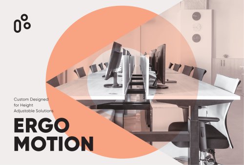
 Catalog Ergo Motion
76 Pages
 Catalog Industrial Motion
92 Pages
 Catalog Comfort Motion
28 Pages
 Catalog Care Motion
36 Pages
 TA50
TA508 Pages
 TFL33S
6 Pages
 TCH2P
TCH2P3 Pages
 JP6-A
JP6-A6 Pages
 JP5-A
JP5-A7 Pages
 TFL10-B
6 Pages
 TL41K-D
6 Pages
 MA6
MA68 Pages
 VN3 series
6 Pages
 MA2
MA27 Pages
 TIP1 series
4 Pages
 TC22 series
3 Pages
 TA38M series
7 Pages
 T-SMART ACTUATOR SOLUTION
4 Pages
 MA3
MA38 Pages
 MA4
MA48 Pages
 VN1
VN112 Pages
 TA48
TA486 Pages
 TA16
TA169 Pages
 TA4
TA411 Pages
 TA38
TA387 Pages
 TA2
TA210 Pages
 TA2P
TA2P12 Pages
 JP4
JP47 Pages
 JP3
JP37 Pages
 TVL3
TVL34 Pages
 TL18AC
7 Pages
 TL15
TL155 Pages
 TL14
TL145 Pages
 TL13
TL135 Pages
 TL12
TL126 Pages
 TL11
TL115 Pages
 TL10
TL105 Pages
 TL9K
TL9K5 Pages
 TL8
TL85 Pages
 TL5
TL56 Pages
 TL3
TL312 Pages
 TGM7
TGM75 Pages
 TGM5
TGM55 Pages
 TGM4
TGM47 Pages
 TGM3
TGM36 Pages
 TGM2
TGM27 Pages
 TGM1
TGM17 Pages


Archived catalogs
 Catalogue Care Motion
36 Pages
 Catalogue Industrial Motion
88 Pages
 Catalogue Ergo Motion
64 Pages
 Comfort Motion guide
28 Pages
 Comfort Motion
28 Pages
 MA2T
MA2T72 Pages
 Care Motion Catalog
32 Pages
 IndustrialMotion_EN
72 Pages
 Ergo Motion Catalog
44 Pages
 Industrial Motion
56 Pages
- TiMOTION cylinder
- TiMOTION actuator
- TiMOTION gear-motor
- TiMOTION linear actuator
- TiMOTION electric actuator
- Double-acting cylinder
- TiMOTION DC gear-motor
- Industrial remote control
- Remote control with buttons
- Compact actuator
- Screw actuator
- Right angle electric gearmotor
- Industrial electric gearmotor
- TiMOTION 24 V gear-motor
- Compact gear-motor
- TiMOTION industrial actuator
- Solid-shaft gear-motor
- Gear train gearmotor
- TiMOTION DC actuator
- TiMOTION compact cylinder