TA2P
1 /12Pages

TA2P
1 /12Pages
Catalog excerpts
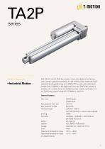
Product Segments • Industrial Motion Both the TA2 and the TA2P are compact, robust, and capable of performing well in certain outdoor environments. A more powerful motor makes the TA2P capable of handling load ratings up to 3500N (787 pounds) while retaining its compact size. In addition to the high power motor, the TA2P linear actuator is available with multiple choices for feedback sensors. Industry certifications for the TA2P linear actuator include IEC / ES 60601-1 and UL73. General Features Max. load Retracted length (with Hall sensors or without output signals) POT, Reed or Hall sensors Color Silver Operational temperature range Operational temperature range
Open the catalog to page 1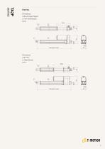
Dimensions without Output Signal or with Hall Sensors (mm) Dimensions with POT or Reed Sensor (mm)
Open the catalog to page 2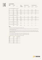
Load and Speed CODE Self Locking Force (N) Motor Speed (5200RPM, duty cycle 25%) A Motor Speed (6600RPM, duty cycle 25%) F Motor Speed (3800RPM, duty cycle 25%) S Motor Speed (2200RPM, duty cycle 25%) T Note 1 Please refer to the approved drawing for the final authentic value. 2 This self-locking force level is reached only when a short circuit is applied on the terminals of the motor. All the TiMOTION control boxes have this feature built-in. 6 The current & speed in table are tested with 24V DC motor. With a 12V DC motor, the current is approximately twice the current measured in 24V DC....
Open the catalog to page 3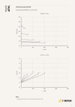
Motor Speed (5200RPM, duty cycle 25%) Speed vs. Load 60.0 Note 1 The performance data in the curve charts shows theoretical value.
Open the catalog to page 4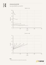
Motor Speed (6600RPM, duty cycle 25%) Speed vs. Load 60.0 Note 1 he performance data in the curve charts shows theoretical value. T
Open the catalog to page 5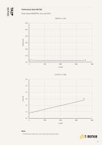
Motor Speed (3800RPM, duty cycle 25%) Speed vs. Load 60.0 Note 1 he performance data in the curve charts shows theoretical value. T
Open the catalog to page 6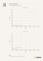
Motor Speed (2200RPM, duty cycle 25%) Speed vs. Load 60.0 Note 1 he performance data in the curve charts shows theoretical value. T
Open the catalog to page 7
Rear Attachment (mm) See page 10 1 = luminum casting, hole 6.4, one piece casting with A gear box 2 = luminum casting, hole 8.0, one piece casting with A gear box 3 = luminum casting, hole 10.0, one piece casting with A gear box 4 = luminum casting, U clevis, slot 6.0, depth 10.5, hole A 6.4, one piece casting with gear box 5 = luminum casting, U clevis, slot 6.0, depth 10.5, hole A 8.0, one piece casting with gear box 6 = luminum casting, U clevis, slot 6.0, depth 10.5, hole A 10.0, one piece casting with gear box Front Attachment (mm) See page 11 1 = luminum casting, hole 6.4 A 2 = luminum...
Open the catalog to page 8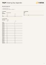
TA2P Ordering Key Appendix Retracted Length (mm) 1. Calculate A+B+C = Y 2. Retracted length needs to ≥ Stroke + Y A. Attachment Front Attachment B. Load V.S. Stroke Stroke (mm)
Open the catalog to page 9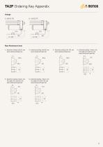
TA2P Ordering Key Appendix Voltage 5 = 24V DC, PTC 4 = luminum casting, U clevis, slot A 6.0, depth 10.5, hole 6.4, one piece casting with gear box 5 = luminum casting, U clevis, slot A 6.0, depth 10.5, hole 8.0, one piece casting with gear box 15 6 = luminum casting, U clevis, slot A 6.0, depth 10.5, hole 10.0, one piece casting with gear box 15 3 = luminum casting, hole 10.0, one A piece casting with gear box 2 = luminum casting, hole 8.0, one A piece casting with gear box 1 = luminum casting, hole 6.4, one A piece casting with gear box
Open the catalog to page 10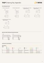
TA2P Ordering Key Appendix Front Attachment (mm) 2 = luminum casting, hole 8.0 A 3 = Aluminum CNC, U clevis, slot 6.0, 4 = luminum CNC, U clevis, slot 6.0, A depth 16.0, hole 6.4 1 = luminum casting, hole 6.4 A 5 = luminum CNC, U clevis, slot 6.0, A depth 16.0, hole 8.0 Direction of Rear Attachment (Counterclockwise) 1 = 90° Functions for Limit Switches Wire Definitions CODE extend (VDC+) 5 (Yellow) retract (VDC+) extend (VDC+) retract (VDC+) extend (VDC+) upper limit switch retract (VDC+) lower limit switch extend (VDC+) upper limit switch medium limit switch retract (VDC+)
Open the catalog to page 11
TA2P Ordering Key Appendix Connector 1 = DIN 6P, 90° plug Terms of Use The user is responsible for determining the suitability of TiMOTION products for a specific application. TiMOTION products are subject to change without prior notice.
Open the catalog to page 12All TiMOTION Europe catalogs and technical brochures
 Catalog Ergo Motion
76 Pages
 Catalog Industrial Motion
92 Pages
 Catalog Comfort Motion
28 Pages
 Catalog Care Motion
36 Pages
 TA50
TA508 Pages
 TFL33S
6 Pages
 TCH2P
TCH2P3 Pages
 JP6-A
JP6-A6 Pages
 JP5-A
JP5-A7 Pages
 TFL10-B
6 Pages
 TL41K-D
6 Pages
 MA6
MA68 Pages
 VN3 series
6 Pages
 MA2
MA27 Pages
 TIP1 series
4 Pages
 TC22 series
3 Pages
 TA38M series
7 Pages
 T-SMART ACTUATOR SOLUTION
4 Pages
 MA3
MA38 Pages
 MA4
MA48 Pages
 VN1
VN112 Pages
 TA48
TA486 Pages
 TA16
TA169 Pages
 TA4
TA411 Pages
 TA38
TA387 Pages
 TA2
TA210 Pages
 JP4
JP47 Pages
 JP3
JP37 Pages
 TVL3
TVL34 Pages
 TL18AC
7 Pages
 TL17
TL179 Pages
 TL15
TL155 Pages
 TL14
TL145 Pages
 TL13
TL135 Pages
 TL12
TL126 Pages
 TL11
TL115 Pages
 TL10
TL105 Pages
 TL9K
TL9K5 Pages
 TL8
TL85 Pages
 TL5
TL56 Pages
 TL3
TL312 Pages
 TGM7
TGM75 Pages
 TGM5
TGM55 Pages
 TGM4
TGM47 Pages
 TGM3
TGM36 Pages
 TGM2
TGM27 Pages
 TGM1
TGM17 Pages


Archived catalogs
 Catalogue Care Motion
36 Pages
 Catalogue Industrial Motion
88 Pages
 Catalogue Ergo Motion
64 Pages
 Comfort Motion guide
28 Pages
 Comfort Motion
28 Pages
 MA2T
MA2T72 Pages
 Care Motion Catalog
32 Pages
 IndustrialMotion_EN
72 Pages
 Ergo Motion Catalog
44 Pages
 Industrial Motion
56 Pages
- TiMOTION cylinder
- TiMOTION gear-motor
- TiMOTION electric actuator
- Double-acting cylinder
- TiMOTION DC gear-motor
- Industrial remote control
- Remote control with buttons
- Compact actuator
- Screw actuator
- Right angle electric gearmotor
- Industrial electric gearmotor
- TiMOTION 24 V gear-motor
- Compact gear-motor
- Solid-shaft gear-motor
- TiMOTION industrial actuator
- Gear train gearmotor
- TiMOTION DC actuator
- TiMOTION compact cylinder