 Website:
TiMOTION Europe
Catalog excerpts

Product Segments • Industrial Motion Engineered by a unique design by TiMOTION, the MA6 series linear actuator is an excellent solution for applications that require heavy duty and incredible durability. Offering a high degree of protection up to IP69K, the MA6 can be constructed to withstand high-pressure water jets, ingress of dust, and other solid contaminants. Depending on the user's application requirements, the MA6 is customizable with a variety of feedback options for improved control and accuracy of motion. Robust, solid, and powerful, the MA6 is ideal for agricultural, commercial, and industrial applications such as combine harvesters, balers, lawn mowers, material handling equipment, livestock ventilation systems, and much more. General Features Max. load Max. speed at max. load Max. speed at no load Retracted length IP rating Stroke Output signals Voltage Operational temperature range Operational temperature range at full performance Manual drive 8,000N (push/pull) 6.2mm/s 64mm/s > Stroke + 162mm IP69K 25~1000mm Hall sensor(s), mechanical Pot., adjustable Reed switch, NPN Hall sensors 12/24V DC; 12/24V DC (thermal switch) -40°C~+85°C +5°C~+45°C
Open the catalog to page 1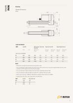
Drawing Standard Dimensions (mm) Load and Speed CODE Load (N) Self Locking Duty Cycle Typical Current (A) Typical Speed (mm/s) Force (N) Push Pull Mechenical No Load With Load No Load With Load Note 1 Please refer to the approved drawing for the final authentic value. 2 The current & speed in table are tested with 24V DC motor. With a 12V DC motor, the current is approximately twice the current measured in 24V DC; speed will be similar for both voltages. 3 The current & speed in table are tested when the actuator is extending under push load. 4 The current & speed in table and diagram are...
Open the catalog to page 2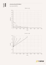
Performance Data (24V DC Motor) Motor Speed (5100RPM) Speed vs. Load
Open the catalog to page 3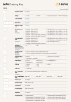
Voltage Load and Speed 1 = 12V DC 2 = 24V DC 6 = 12VDC, thermal switch 5 = 24VDC, thermal switch Stroke (mm) Retracted Length (mm) Rear Attachment (mm) See page 6 Front Attachment (mm) See page 6-7 Direction of Rear Attachment (Counterclockwise) See page 7 Function of Limit Switches See page 8 Adjustable Reed Switch Output Signal 1 = #45 Steel, slotless, hole 10.2 2 = #45 Steel, slotless, hole 12.2 3 = #45 Steel, slotless, hole 12.8 4 = #45 Steel, U clevis, slot 8.2, depth 12.5, hole 10.2 5 = #45 Steel, U clevis, slot 8.2, depth 12.5, hole 12.2 1 = #45 Steel, slotless, hole 10.2 2 = #45...
Open the catalog to page 4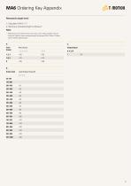
MA6 Ordering Key Appendix Retracted Length (mm) 1. Calculate A+B + C = Y 2. Minimum retracted length is Stroke+Y Note 1 Depending on the attachments, the motor cover might interfere with the customer's device when retracted length is between 225~318mm. Please confirm before placing order. Front Rear Attach. Output Signal B. Stroke (mm) Load & Speed Type (N) B, C, D, E 25~150 -
Open the catalog to page 5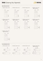
MA6 Ordering Key Appendix Rear Attachment (mm) 1 = #45 Steel, slotless, hole 10.2 2 = #45 Steel, slotless, hole 12.2 3 = #45 Steel, slotless, hole 12.8 4 = #45 Steel, U clevis, slot 8.2, depth 12.5, hole 10.2 12.5 010.2 5 = #45 Steel, U clevis, slot 8.2, depth 12.5, hole 12.2 12.5 012.2 6 = #45 Steel, U clevis, slot 8.2, depth 12.5, hole 12.8 7 = #45 Steel, U clevis, slot 8.2, depth 15.0, hole 10.2 15 010.2 8 = #45 Steel, U clevis, slot 8.2, depth 15.0, hole 12.2 15 012.2 9 = #45 Steel, U clevis, slot 8.2, depth 15.0, hole 12.8 15 012.8 7 = #45 Steel, U clevis, slot 8.2, depth 15.0, hole 10.2
Open the catalog to page 6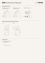
MA6 Ordering Key Appendix Front Attachment (mm) 9 = 45 Steel, U clevis, slot 8.2, # depth 15.0, hole 12.8 8 = 45 Steel, U clevis, slot 8.2, # depth 15.0, hole 12.2 Direction of Rear Attachment (Counterclockwise) 3 = 90° Connector (mm) 01 = inned leads, unsheathed wire T 50, stripped w
Open the catalog to page 7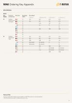
qo t moTion Wire Definition Normal Port Function of Wire Color Number Limit Switches Two Micro Switches Cut Off The Actuator Two Micro Switches Send Signal Output Signal 0. Without EXT+ RET+ EXT+ EXT+ EXT+ RET+ RET+ RET+ EXT+ RET+ COM EOS-extended EOS-retracted EXT+ EXT+ EXT+ RET+ RET+ RET+ V-out EOS-retracted EOS-retracted Terms of Use The user is responsible for determining the suitability of TiMOTION products for a specific application. TiMOTION products are subject to change without prior notice.
Open the catalog to page 8All TiMOTION Europe catalogs and technical brochures
-
TA50
8 Pages
-
TFL33S
6 Pages
-
TCH2P
3 Pages
-
JP6-A
6 Pages
-
JP5-A
7 Pages
-
TFL10-B
6 Pages
-
TL41K-D
6 Pages
-
VN3 series
6 Pages
-
MA2
7 Pages
-
TIP1 series
4 Pages
-
TC22 series
3 Pages
-
TA38M series
7 Pages
-
T-SMART ACTUATOR SOLUTION
4 Pages
-
IndustrialMotion_EN
72 Pages
-
MA3
8 Pages
-
MA4
8 Pages
-
VN1
12 Pages
-
TA48
6 Pages
-
TA16
9 Pages
-
TA4
11 Pages
-
TA38
7 Pages
-
TA2
10 Pages
-
TA2P
12 Pages
-
JP4
7 Pages
-
JP3
7 Pages
-
TVL3
4 Pages
-
TL18AC
7 Pages
-
TL17
9 Pages
-
TL15
5 Pages
-
TL14
5 Pages
-
TL13
5 Pages
-
TL12
6 Pages
-
TL11
5 Pages
-
TL10
5 Pages
-
TL9K
5 Pages
-
TL8
5 Pages
-
TL5
6 Pages
-
TL3
12 Pages
-
TGM7
5 Pages
-
TGM5
5 Pages
-
TGM4
7 Pages
-
TGM3
6 Pages
-
TGM2
7 Pages
-
TGM1
7 Pages
-
Comfort Motion
28 Pages
-
Industrial Motion
56 Pages
-
Care Motion Catalog
32 Pages
-
Ergo Motion Catalog
44 Pages
Archived catalogs
-
MA2T
72 Pages


