Timken Industrial Seal Technical Manual
1 /60Pages

Timken Industrial Seal Technical Manual
1 /60Pages
Catalog excerpts
Timken Industrial Seal Technical Manual High Performance Seals • Large Bore Assembled Seals • Bearing Isolator
Open the catalog to page 1
At Timken, customers turn to us to for innovative solutions that solve their most critical issues. When they do, they benefit from more than a century of knowledge in managing friction and transmitting power for a variety of industries and applications. We've applied this technical know-how to offer OEMs, distributors and end users a complete line of products and services - from bearings, maintenance tools and condition monitoring products to engineered surfaces, training programs, bearing and chock repair, and more. Now, from the people that brought you Timken industrial seals for small bore...
Open the catalog to page 3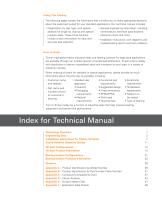
Using This Catalog The following pages contain the information that will allow you to make appropriate decisions about the seals best suited for your standard applications. Our technical manual includes: Organization by seal type, with special sections for single lip, dual lip and special purpose seals. These three sections include critical information for easy and accurate seal selection. • General engineering information, including nomenclature, technical specifications, tolerance charts and more. • Installation instructions, with diagrams, and troubleshooting tips for common problems. Timken...
Open the catalog to page 4
Technology Overview Technology Overview Timken Nitrile (N) Black Industrial Seals Taber Abrasion Resistance (ASTM D4060) Wear Index (mg/1000 loss) Oil Seals Creating the most advanced seals for heavy industrial markets requires quality materials. Timken industrial seals are manufactured using special elastomers that are engineered for high-abrasion resistance, low wear and outstanding temperature and chemical resistance. In addition, we have materials and designs suited for a wide range of applications and our color-coded seals help you identify the seal to ensure you are using the right seal...
Open the catalog to page 5
General Specifications Timken industrial seals offer a leading combination of quality, technology and high performance. However, there are additional considerations - such as shaft finish, temperatures and other operating factors -that can impact the level of performance achieved. We recommend the following practices to ensure that you are maximizing the efficiency and the life of your bearings and machinery. For specific application assistance, contact your Timken sales representative. Shaft Finish The amount of contact between the shaft surface and the sealing element, and the condition of...
Open the catalog to page 6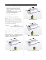
Engineering Data Engineering Data 6. Adjust machine’s rotational speed to 60 RPM. 7. Measure the axial movement of the thread while the shaft or sleeve rotates for a period of 30 seconds. 8. Look for movement at both edges of the shaft by placing the thread there as well. 9. Reverse the direction of the shaft or sleeve rotation and repeat the test. 10. Refer to Table 2 to determine results. Comparing Shaft Lead – Lead Angle The lead of a shaft is compared with other shafts of differing diameters by calculating the lead angle. This is found by dividing the string advance by the product of the...
Open the catalog to page 7
Shaft-to-Bore Misalignment Shaft-to-bore misalignment is the distance by which a shaft is off center relative to its bore. To measure this, calculate the distance between the shaft center line and the bore centerline, as shown in Figure 5. Dynamic Runout Dynamic runout is the amount by which a shaft, at the sealing surface, does not rotate around the true center. You can measure dynamic runout by holding a dial indicator against the shaft surface while it is slowly rotated. The resulting measurement is called a total indicator reading, or TIR. See Figure 6. Pressure Data Table 3 shows the maximum...
Open the catalog to page 8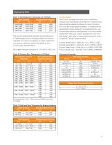
Table 5: Shaft Diameter Tolerances for Oil Seals
Open the catalog to page 9
Model 145 Face Seal Dimensional Data DIM # IMPORTANT NOTE Recommendations printed in this catalog pertaining to shaft finishes, misalignment, runout, speeds, temperatures and tolerances are generally applicable. The combination of a selected seal with a certain application, and the operating circumstances involved, could modify the performance of the seal and/or the equipment. To get the most out of your Timken seals, submit full information to ensure that the seal(s) you receive are suitable for your application.
Open the catalog to page 10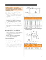
Equipment Inspection and Preparation Before installing any lip seal, equipment should be thoroughly inspected. Follow the specifications below for best results: Shaft Surface Finish [Roughness Average or AA (Arithmetic Average)] • With the exception of PS-1 (Model 61), all shafts should have a surface finish within 10-20 pin. (0.25-0.50 pm). • For PS-1 (Model 61), the surface finish should be within 4-8 p in (0.10-0.20 pm). • The surface finish direction of all seals must be perpendicular to the shaft axis of rotation. Bore Surface Finish, Ra ([Roughness Average or AA (Arithmetic Average)] •...
Open the catalog to page 11
Installation Instructions Seals • Typically, the shaft has a wear groove created from previous seals. Make sure the new sealing lip does not seal in the same location. • When drive features such as keyways or splines are present, they must be covered using an installation tool similar to the one shown in Figure 10 below, and using “Installation Method D” shown in Figure 10 on the next page. If the use of a tool is prohibited by the size of the shaft, use one of the following options: Installation Methods Installation Method A Thru Bore: Installation tool bottoms on machined face Installation...
Open the catalog to page 12
Seals Installation Instructions • Continue by rotating the wooden block to the appropriate positions (3 and 4, 5 and 6, 7 and 8), hitting the center of the block with the mallet each time. IMPORTANT NOTE The 0.015 in. protrusion will be built into the width of the seal. The depth of the bore housing should be machined to the seal width specified on the package. • Repeat the pattern until the seal is properly seated in the housing bore. The seal is fully seated when the difference between the seal surface and the housing surface is equal to or less than 0.010 in. (0.254 mm). Split Seal Installation...
Open the catalog to page 13All TIMKEN catalogs and technical brochures
 National® Industrial Seals
716 Pages
 TIMKEN® ECOTURN® SEAL
2 Pages
 Timken® Lubricants
6 Pages
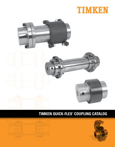
 Quick-Flex Couplings
68 Pages
 Matched Bearing Assemblies
16 Pages
 Cylindrical Roller Bearings
108 Pages
 AP Bearings
84 Pages
 UC Series Ball Housed Units
24 Pages
 Type E Housed Units
40 Pages
 Ball Housed Units
180 Pages
 SNT Plummer Blocks
120 Pages
 SAF Housed Units
126 Pages
 Thrust Bearings
138 Pages
 Quick-Flex Coupling Catalog
68 Pages
 Bearing interchange guide
163 Pages
 UC-SERIES
24 Pages
 Commercial Vehicle Catalog
417 Pages
 Quick-Flex Coupling
64 Pages
 Timken Drives Roller Chain Catalog
112 Pages
 Industrial Maintenance Manual
157 Pages
 Timken SAF Housed Unit Catalog
126 Pages
 Timken Ball Housed Unit Catalog
180 Pages
 Timken® SNT Plummer Block Catalog
120 Pages
 BALL BEARINGS
214 Pages


Archived catalogs
 Timken Engineering Manual
210 Pages
 Timken Ball Bearings Catalog
217 Pages
 COMPETENCYBASED TRAINING
5 Pages
 Spherical Roller Bearings
236 Pages
 Timken Industrial Seals
40 Pages
 Ball Bearings
6 Pages
 IsoClass Bearings
8 Pages
 Maintenance Tools
16 Pages
 Industrial Products
56 Pages
 Precision Rotary Assemblies
2 Pages
 Ceramic Bearings
2 Pages


- TIMKEN steel bearing
- Synthetic lubricant
- Plastic seal
- TIMKEN ball bearing
- TIMKEN radial bearing
- Anti-corrosion lubricant
- Bearing lubricant
- TIMKEN single-row bearing
- TIMKEN roller bearing
- High-temperature lubricant
- Toroidal seal
- Lipped gasket
- TIMKEN precision bearing
- Plain bearing
- Bearing grease
- Metal lubricant
- TIMKEN axial bearing
- Long-life lubricant
- Round seal