Catalog excerpts

US $10 SSG TIMKEN SE A L SPE CIF ICATION GUIDE A LEADER IN SEAL TECHNOLOGY SEALS Inch/Metric V-Seals Oil Bath Seals KWIK-Sleeves™ - Components Seal Kits O-Rings SE A L S PE C IF I CAT ION G UID E Timken® is the registered trademark of The Timken Company. www.timken.com www.timkeninfo.com © 2001 The Timken Company Printed In the U.S.A. 60M-12-01-11 Order No. 7533 WORLDWIDE LEADER IN BEARINGS AND STEEL THE TIMKEN COMPANY
Open the catalog to page 1
SEAL SPECIFICATION GUIDE The Timken Company, known for its top-quality line of bear- ings, has extended its product line to include seals. Timken, with 77 seal patents, already had the product knowledge for seal design. In fact, it was only natural for Timken to extend this experience into a complete line of seals for the automo- tive aftermarket. Each and every seal sold by Timken is man- ufactured with the same quality that goes into every Timken bearing. To help our customers in seal selection, we have developed this Seal Specification Guide. If you have com- ments or suggestions on the...
Open the catalog to page 2
SECTION PAGE
Open the catalog to page 3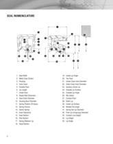
SEAL NOMENCLATURE 2. Metal Case (Outer) 8. Radial Wall Dimension 9. Seal Outer Diameter 10. Housing Bore Diameter 11. Spring Position (R-Value) 21. Inside Case Inner Diameter 22. Outer Case Inner Diameter 32. Free Lip (Unsprung) Diameter 33. Contact Line Height
Open the catalog to page 4
SEAL DESIGN/TYPES
Open the catalog to page 5
peci ficati SHAFT RECOMMENDATIONS Seal and shaft compatibility is dependent on four conditions: shaft tolerance, lead-in chamfer, finish and hardness. Proper consideration of these conditions will assist in providing optimal seal performance. • SHAFT HARDNESS is an important factor to prevent excessive wear, deformation, scratches or nicks, and to allow for easy machining for proper roughness. Under normal conditions, the seal contact area of the shaft should be Rockwell C45 minimum. • SHAFT SURFACE ROUGHNESS is very important as this greatly influences the amount of lip wear. The...
Open the catalog to page 7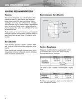
SEAL SPECIFICATION GUIDE HOUSING RECOMMENDATIONS Steel and cast iron provide good surfaces for both rubber covered and metal O.D. seals. For soft alloy (aluminum) bores, rubber covered O.D. seals provide better sealing capability. In aluminum or other soft alloy bores, metal O.D. seals occasionally back out of the bore due to thermal expan- sion of the soft alloy. Rubber, having a higher coefficient of thermal expansion than carbon steel, will tighten in the bores Plastic or nylon are not recommended because they typically expand at a high rate causing a major problem for metal O.D. seals....
Open the catalog to page 8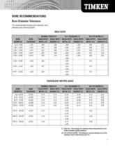
BORE RECOMMENDATIONS Bore Diameter Tolerance The recommended housing bore diameter, bore tolerance and nominal pressfit. INCH SIZES EQUIVALENT METRIC SIZES (1) Seal O.D. - The average of a minimum three measurements to be taken at equally spaced positions. (2) Out of Round (OOR) - The maximum variance between any of the readings used in determining seal O.D.
Open the catalog to page 9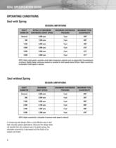
SEAL SPECIFICATION GUIDE OPERATING CONDITIONS Seal with Spring DESIGN LIMITATIONS NOTE: Higher shaft speed is possible using higher temperature materials such as polyacrylate, fluoroelastomer or silicone. Slightly higher continuous pressure is possible for shaft speeds below 200 fpm. Higher eccentricity is allowable if shaft speed is reduced. Seal without Spring DESIGN LIMITATIONS NOTE: Higher eccentricity is allowable if maximum shaft speed is reduced. A nonsprung seal design offers a cost effective way to seal high viscosity grease applications. Because the design does not benefit from...
Open the catalog to page 10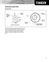
OPERATING CONDITIONS de=Dynamic Eccentricity Eccentricity is determined by measuring the shaft runout, TIR and the shaft-to-bore misalignment. Combine the two results for the total eccentricity the seal lip must follow to function effectively. As eccentricity increases, and/or shaft speed increases, it becomes more difficult for the lip to follow the
Open the catalog to page 11
SEAL SPECIFICATION GUIDE SEAL TOLERANCES To provide an interface between the seal outside surface and the housing bore surface, the recommended tolerances for the outside diameter of the seal are indicated below. Seal width tolerance Values in millimeters SEAL OUTSIDE DIAMETER TOLERANCES 1 ) The roundness tolerance is equal to the difference between the maximum diameter and the minimum diameter derived from three or more equally spaced measurements. 2) Rubber-covered seals having a wave profile outside surface are acceptable but will require different tolerances to be agreed upon between...
Open the catalog to page 12
specific ajfe MATERIAL SELECTION General Elastomer Information Felt (F) - Adequate seal for heavier lubricants, commonly used as a wiper seal. Urethane (U) - Good lubricant resistance, good ozone resistance, good abrasion resistance Tetrafluoro-Ethylene Propylene (Aflas8) (A) - Compatible with range of hydraulic fluids, fair abrasion resistance P.T.F.E. (Teflon8) (T) - Low friction properties, good heat and chemical resistance TEFLON*, VAMAC* and VITRON* are registered trademarks of E.I. Dupont. AFLAS® is a registered trademark of the 3M Company.
Open the catalog to page 13
SEAL SPECIFICATION GUIDE SEAL INSTALLATION PROCEDURES The subject of installation represents an area commonly overlooked when selecting an oil seal for an application. Studies have shown this area to be one of the major causes of premature seal failure. To assist the installation, the seal should be prelubricated with grease or oil to reduce sliding friction of contact surfaces. This will also help protect the seal lips during initial run-in. An installation tool should always be used when installing an oil seal. The use of a tool improves ease of installation and reduces the possibility of...
Open the catalog to page 14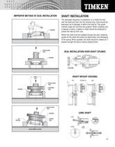
IMPROPER METHOD OF SEAL INSTALLATION HOUSING SHAFT INSTALLATION The advisable sequence of installation is to install the seal over the shaft and then into the housing bore. Care should be exercised not to damage or deform the seal lip. The proper chamfer angle will minimize this problem. When installing over a keyway or spine, a sleeve or bullet should be employed to protect the seal lip from cuts. Where the shaft must be installed through the seal, centering guides for the shaft will prevent lip deformation and dislodging of the spring. When possible, the shaft should be rotated as it...
Open the catalog to page 15All TIMKEN catalogs and technical brochures
-
National® Industrial Seals
716 Pages
-
TIMKEN® ECOTURN® SEAL
2 Pages
-
Timken® Lubricants
6 Pages
-
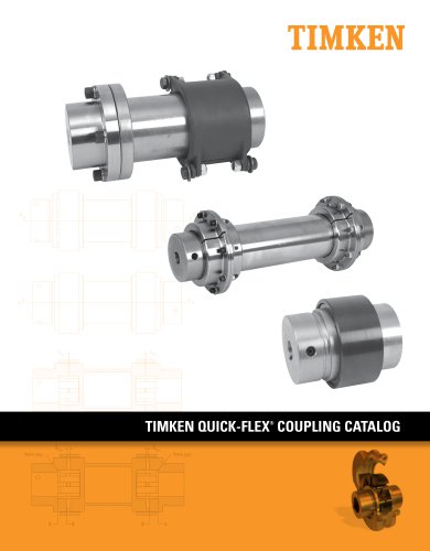
Quick-Flex Couplings
68 Pages
-
Matched Bearing Assemblies
16 Pages
-
Cylindrical Roller Bearings
108 Pages
-
AP Bearings
84 Pages
-
UC Series Ball Housed Units
24 Pages
-
Type E Housed Units
40 Pages
-
Ball Housed Units
180 Pages
-
SNT Plummer Blocks
120 Pages
-
SAF Housed Units
126 Pages
-
Thrust Bearings
138 Pages
-
Quick-Flex Coupling Catalog
68 Pages
-
Bearing interchange guide
163 Pages
-
UC-SERIES
24 Pages
-
Quick-Flex Coupling
64 Pages
-
Timken Drives Roller Chain Catalog
112 Pages
-
Commercial Vehicle Catalog
417 Pages
-
Industrial Maintenance Manual
157 Pages
-
Timken SAF Housed Unit Catalog
126 Pages
-
Timken Ball Housed Unit Catalog
180 Pages
-
Timken® SNT Plummer Block Catalog
120 Pages
-
BALL BEARINGS
214 Pages
Archived catalogs
-
COMPETENCYBASED TRAINING
5 Pages
-
Spherical Roller Bearings
236 Pages
-
Timken Engineering Manual
210 Pages
-
Timken Ball Bearings Catalog
217 Pages
-
Timken Industrial Seals
40 Pages
-
Ball Bearings
6 Pages
-
IsoClass Bearings
8 Pages
-
Maintenance Tools
16 Pages
-
Industrial Products
56 Pages
-
Precision Rotary Assemblies
2 Pages
-
Ceramic Bearings
2 Pages


