GSA1 Series
1 /15Pages

GSA1 Series
1 /15Pages
Catalog excerpts
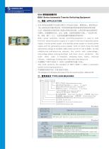
GSA1 Series Automatic Transfer Switching Equipment GSA1 series automatic transfer switching equipment is used to shift from the abnormal power supply to in case of one line of abnormal power supply ( normal power supply and standby power supply or normal power supply and the generating power supply), both of which have the rated operational voltage of AC400V, 50Hz,rated current of 1 OA to 800A , So that reliablity and continuous are ensured . this switch with undervoltage , overvoltage phaes missing,overload and short circuit protection . this swith often used in hospitalsx shopping mallsx banksx chemica ndustryx metallurgy .building other importanr sites electricity. This swith performs the standard of GB/T 14048.1 1-2002 << Automatic tansfer switching equipment>>. Tha category of utilisation and class of this this switch are AC-33B and CB. ~» ig^&SX TYPE AND MEANING §53iIfPE&)]S Rated operational current Neutral poles of foue poles code (See table 1) - KiS(Pole number): 3:three poles 4: four poles - IfP7jlClAl?S5 Work ways see table 5 FffiType R SSType S FSType F '- lb?J^Sy]Al^2: Ability class see table 2: L:f/j\)tlJ BasicType M^SESf High level Type H:JBiTlSJ Communicative Type '- |f?SS§§?S^^ISIi5^^)jS Rate frame current of the breaker - fSvtS^ Design code '- ffisFF^: Automatic Transfer Switch - Enterprises code
Open the catalog to page 1
The ambient temperature is- 5°C ~ + 40°C and the average value within 24hours isn't above +35°C The relative hunidity ofthe air isn't avobe 50% at the max , temperature of+40°C, average temperature isn't avobe+25°C at the max,hunidity, and the average relative hunidity isn't avobe 90%, Dew on swith due to temperature alteration should be removed. LCD displays: Nameplate pages can be shownx setting parameters pagesN running pageSx memory pages and so on , each page shows a different function , man and machine can be achieved to dialogue on display and buttons. Password settiing: setting parameters...
Open the catalog to page 2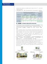
normal power supply and standby power supply switch off , two power A HSW^aSSMPlAlb: JflH30 Overload and short-circuit protection: see table 3. 2u ISftiftQl STRUUCTURE EXPLAINATION GSA1 automatic switch is the automatic switching devices that consists of tha main body and the controller, the main body consists of two sets of GSM1 breakers with the same frame cuurrent and equipped with motordriven device , mechanical interlock and appendixes, All the components are installed on a metal plate, The controller has two type: integral (see picturel), split(see picture2). GSA1 can be divided into integral...
Open the catalog to page 3
7\. JS##&J&S TECHNICAL PARAMETERS (SEE TABLE) Limiting short-circuit breaing ability Operation short-circuit brea king abi lity Rated work- Rated work- tion voltage ?H , ' life -undervoltageovf voltaf less than ISflJ??EtfniE?7*gEt CONTROL TYPE AND OPERATION MODE Control ways and operation mode see table 5 fg;(table)5
Open the catalog to page 4
Normal power operating modes for type Fk type Sx type F: Press "normal key" , as normal power has connected, the system not operating separately,as standby power has connected,the system immediately disconnect standby breaker. Normal breaker close after delay time, if normal power opeared malf- unction,normal power will be disconnected after delay time. Standby power operating modes for type Rx type Sx type F: Press "standby key" , as standby power has connected, the system not operating separately,as normal standby power has connected,the system immediately disconnect normal breaker, standby...
Open the catalog to page 5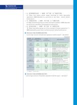
t4: Delay time before power supply switching on while restorating operationd -999S,Adjusted by users,time is set three second before factory price ) t5: Delay time before giving out of the command of unloadd -999S, Ad justed by users time is set three second before factory price ) T6: Delay time before giving out of the command of power generation d- 999S,Adjusted by users,time is set three second before factore price ) Control logic function of Automatic operation mode for type R (seetable6) Control logic function of Automatic operation mode for type S (see table 7)
Open the catalog to page 6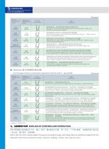
fSffllMffftW EXPLAN OF CONTROLLER OPERATION GSA1 LED controller display pages througt an exchange of page ,each page features adefferent pages from the keyboard and csreen to achieve human-machine dialogue , simple and clear structure.
Open the catalog to page 7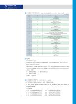
■ ^US^B^MB^^d) sign introduced of controller (see table 9) Nameplate pages LED screen display automatic switch plate and parameters,including ra ted insulation voltage, rated working voltage, rated working current and product type GSAI -rssys It will show phase voltage value of all phase of the two ways of power supply. U1 2 = rftffl ^)J1 Bffiffi ^ffifi U 2 2 = gffl ^)J1 Bmm *JB1 U13 = rftffl ^SCffiffi ^JBl U 23 = gffl ^SCffi^ffifi
Open the catalog to page 8
■ SW$i3tZS7J\f5[!: Error search page: It can memory last power failure(normai power supply or standby power supplyk fault type ( overvoltagex undervoltagex lost voltage^ lacking phase) , fa uit max voltage and min voltage. TYPE-25P»^Sy (QXKi, SY^ffi, GY affi. QY^ffi) ■ iSSEfli Setting page Password value can be changed by " + " key and " - " ,it will can set other projects after password value (password value is 213) equiva- lent setting value, use "confirm" key and move the cursor to the corresponding project, and then use " + " and " - " keys to change its value and complete setting, then press...
Open the catalog to page 9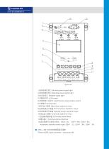
rel ease norrral standby 1 .SfflEfeSlt^I Normal power signal light 2.^fflEgS1ts!ia Standby power signal light 3.Kffllis!l;l Release signal light 5.S3]$^J?5fi:7^fetP\ Identification of automatic switch 7.®T/ffljii:Q}f?i! Open/hook operation keys 8.fflffi^,)Jljsl3}$fii Normal power operation keys 9.^ffl^)Jljsl3}S:Si Standby power operation keys 10.^z^jsfjffjfjl Automatic operation keys 11 .SffjlJgS^,)lKSi Controller power keys Panel of GSA1 split controller (see picture 6)
Open the catalog to page 10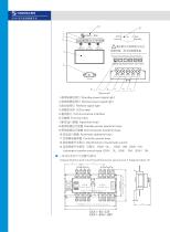
Kffl Sffl release normal standby normal standby 3lease open automatic transfer switch entering wire of power, then connected with the controller. 1 ■ffl'ffl^S'lfts^J Standby power signal light 2.^fflE&Sfli§!0' Normal power signal light 3JKffllts!l;l Release signal light S.SS^Sjs^Sii Standby power operation keys 9-^ffl^SjsfrS?§l Normal power operation keys 1 O.^z^js^}!?!! Automatic operation keys 11 .ffitllgi^SSli Controller power keys 12.§zJ|$?ffi!;H:7^feiP\ Identification of automatic switch Automatic transfer switch type: GSA1 -3U GSA1-3M. GSA1-3H. ntegraI Outline and mounting dimensions see...
Open the catalog to page 11All Tianshui 213 Electrical Apparatus Group CO.,LTD. catalogs and technical brochures
 GSC2-F Range AC Contactor
5 Pages
 CIRCUIT BREAKERS GSB1Z
3 Pages
 GSW1
GSW133 Pages
 GSC1-4011 FC-6511 FC
4 Pages
 GSC3 series
5 Pages
 GSB2
GSB24 Pages
 GSB2-32N
3 Pages
 GSG2 insolated switch
14 Pages
 JZC3-dZ DC Contactor relay
3 Pages
 JZC3 Contactor relay
4 Pages
 CJX4-kd capacity contactor
5 Pages
 molded case circuit breaker
26 Pages


Archived catalogs
 3P AC contactor GSC1
7 Pages
- Circuit breaker
- Protection relay
- Contactor
- Single-pole circuit breaker
- Electric motor protection relay
- Power contactor
- Overload relay
- Mini circuit breaker
- DC contactor
- Electromagnetic contactor
- AC protection relay
- AC contactor
- DIN rail circuit breaker
- Molded case circuit breaker
- Contactor for industrial applications
- Starter
- Auxiliary contactor
- Motor contactor
- Multipole contactor
- Compact contactor