- Products
- Catalogs
- News & Trends
- Exhibitions
NVA100X
1 /20Pages

NVA100X
1 /20Pages
Catalog excerpts
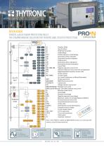
“Something better than protective relays” NVA100X FEEDER, LoM & POWER PROTECTION RELAY THE COMPREHENSIVE SOLUTION FOR FEEDERS AND UTILITIES PROTECTION U L1, U L2, U L3 UE CTs-VTS input ThySensor inputs Overux (V/Hz) Synchrocheck Pt100 thermal probes Undervoltage Positive sequence undervoltage Directional active overpower Directional reactive overpower Undercurrent Directional active underpower Directional reactive underpower Loss of eld Negative sequence overcurrent Neutral unbalance overcurrent with compensation Negative/positive sequence current ratio Phase reversal Thermal image (for Lines/Transformers or Motor/Generators) 50/51 Phase overcurrent 50/51(RMS) RMS Phase overcurrent 51LR(48)/14 Locked rotor 51V Voltage restraint overcurrent 50N/51N/87NHIZ* Residual overcurrent 50N(Comp)/51N(Comp) Calculated residual overcurrent 55 Minimum power factor 59 Overvoltage 59N Residual overvoltage 59V2 Negative sequence overvoltage 66 Maximum number of startings (Restart inhibition) 67 Phase directional overcurrent 67N Ground directional overcurrent DPHI Vector jump 81O/81U Overfrequency and underfrequency 81R Frequency rate of change BF Circuit breaker failure 74CT, 74VT CT-VT supervision 74TCS Trip circuit supervision FL Fault locator 79 Automatic reclosure Note *: when 87NHIZ is enabled, the 50N/51N/67N functions can not be used with residual current (IE) measured directly CONTROL & MONITORING - PLC - TCS - CB MONITORING,.. - SNTP - IRIG-B COMMUNICATION - Modbus RS485 - Modbus TCP/IP - IEC61850 - IEC 870-5-103/DNP3
Open the catalog to page 1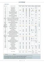
Note I: comparison between a voltage applied to the UE (residual voltage input) and three voltage inputs UL 7, UL2, UL3 Note 2:46 protective function for Lines/Transformers (46LT) or Motor (46M)/Generator (46G) Note 3:49 protective function for Lines/Transformers (49LT) or Motor/ Generator (49MG) Note 4: when 87NHIZis used, the 50N/5IN/67N functions can not be used with residual current (fc) measured directly Note 5: The side (H or L) where the residual current is computed can be select (km or kci)
Open the catalog to page 2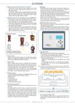
— Measuring inputs with inductive CTs and VTs • Three phase current inputs and one residual current input, with nominal currents independently selectable at 1 A or 5 A through sw setting. • Three phase voltage inputs with programmable nominal voltages within range 50...130 V (UR =100 V) or 200...520 V (UR =400 V) and one residual voltage input, with programmable nominal voltage within range 50...130 V (UER =100 V). — Measuring inputs with ThySensor devices (NVA100X-P) • Three phase current inputs, with 630 A primary rated current. • One residual current input, with nominal currents independently...
Open the catalog to page 3
— Control and monitoring Several predened functions are implemented: • Activation of two set point proles • Phase CTs and VTs monitoring (74CT and 74VT) • Logic selectivity • Cold load pickup (CLP) with block or setting change • Trip circuit supervision (74TCS) • Second harmonic restraint (inrush) • Remote tripping • Synchronization via NTP or IRIG-B (optional) • Automatic reclosing (79) • Fault location • Circuit Breaker commands and diagnostic. Moreover user dened logic must be customized in accordance with IEC 61131-3 protocol by means programmable logic controller (PLC). Circuit Breaker Several...
Open the catalog to page 4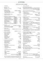
Mechanical data Mass (flush mounting case) Insulation tests Reference standards High voltage test 50Hz Impulse voltage withstand (1.2/50 u.s) Insulation resistance Reference standards — EMC tests for interference immunity 1 MHz damped oscillatory wave Electrostatic discharge Fast transient burst (5/50 ns) Conducted radio-frequency fields Radiated radio-frequency fields High energy pulse Damped oscillatory wave Ring wave Conducted common mode (0...150 kHz) Reference standards Climatic tests Reference standards Mechanical tests Reference standards Safety requirements Reference standards Pollution...
Open the catalog to page 5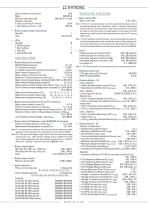
Short duration current (0,5 s) Make Minimum switching load Breaking capacity: • Direct current (L/R = 40 ms) • Alternating current (λ = 0,4) — Block output (Logic selectivity) Quantity Type — LEDs Quantity • ON/fail (green) • Start (yellow) • Trip (red) • Allocatable (red) MAIN SETTINGS — Rated values (all versions) B9-B10 Voltage measure UE or V2 V1-V2 phase correction 0...360 ° V1 voltage measure for synchrocheck element U12 /UL1 Relay nominal frequency (f n) 50, 60 Hz Relay residual nominal current (IEn) 1 A, 5 A Residual CT nominal primary current (IEnp) 1 A...10 kA Relay nominal voltage...
Open the catalog to page 6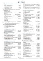
— Thermal protection with PtIOOthermometric probes - 26 Note: The element becomes available when the MPT board is available Common configuration: • Voltage measurement type for 27 (Utype27) • 27 Operating logic [Logic!!) • U<Curve type ((/<Curve) DEFINITE, INVERSE121 Definite time • 27 First threshold definite time [U<M] • U<def Operating time (fu<def) Inverse time • 27 First threshold inverse time (U<\m) • (7<inv Operating time (flj<inv) Definite time • 27 Second threshold definite time (f/«def) 0.05...1.10 U„/E„ • y«def Operating time (fu«def) 0.03...100.0 s Note I: On MMI, with t/ph-ph setting...
Open the catalog to page 7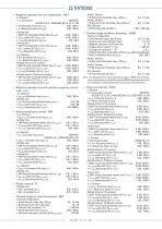
— Negative sequence for Line-Transformer - 46LT I2> Element • I2> Curve type DEFINITE, IEC/BS A, B, C - ANSI/IEEE MI, VI, EI, I2t , EM • CLP Activation time (t 2CLP>) 0.00...100.0 s 0.00...100.0 s • I2> Reset time delay (t 2 > RES) Denite time 0.100...10.00 In • 46LT First threshold denite time (I2 > def ) 0.100...10.00 In • I2 > def within CLP (I2CLP>def ) 0.03...200 s • I2 > def Operating time (t 2 > def ) Inverse time 0.100...10.00 In • 46LT First threshold inverse time (I2 >inv) • I2 >inv within CLP (I2CLP>inv) 0.100...10.00 In • I2 >inv Operating time (t 2 >inv) 0.02...60.0 s I2>> Element...
Open the catalog to page 8All THYTRONIC catalogs and technical brochures
 NA016
NA0168 Pages
 iRTUe
iRTUe4 Pages
 iRTU
iRTU4 Pages
 NA10
NA108 Pages
 PRO-N
PRO-N16 Pages
 TIS
TIS1 Page
 TEST BLOCK SYSTEM - Flyer
8 Pages
 DCL-flyer
8 Pages
 NC020-Flyer
8 Pages
 NA011-Flyer
8 Pages
 Pro N - brochure
12 Pages
 brochure Serie S
4 Pages


Archived catalogs
 Product Flayer
4 Pages
- Current protection relay
- Voltage protection relay
- Digital protection relay
- Electric motor protection relay
- IEC protection relay
- Programmable protection relay
- Panel-mount protection relay
- Overload relay
- Over-current protection relay
- Differential protection relay
- AC protection relay
- Adjustable protection relay
- Over-voltage protection relay
- Generator protection relay
- Under-voltage protection relay
- Time delay protection relay
- RS485 protection relay
- Automatic control panel
- Frequency protection relay