- Products
- Catalogs
- News & Trends
- Exhibitions
NV10P LoM PROTECTION RELAY THE COMPREHENSIVE SOLUTION FOR VOLTAGE AND FREQUENCY PROTECTION
1 /16Pages

NV10P LoM PROTECTION RELAY THE COMPREHENSIVE SOLUTION FOR VOLTAGE AND FREQUENCY PROTECTION
1 /16Pages
Catalog excerpts
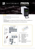
Protection Relays LoM PROTECTION RELAY THE COMPREHENSIVE SOLUTION FOR VOLTAGE AND FREQUENCY PROTECTION — Application The relay type NV10P can be typically used in HV, MV and LV distribution systems, on transformers or for electrical machines. It can be used for system decoupling, load shedding and loss of main (islanding) protection. - Protective & control functions Phase undervoltage Positive sequence undervoltage Phase overvoltage Negative sequence overvoltage Residual overvoltage Average overvoltage Overfrequency Underfrequency Frequency rate of change Circuit breaker failure Trip circuit supervision Automatisms concerning the VTs positioning Automatic reclosure (opzional for pv plants
Open the catalog to page 1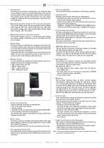
According to the hardware configurations, the protection relay can be shipped in various case styles depending on the required mounting options (flush, projecting mounting, rack or with separate operator panel) and with connections to the input signals suitable for inductive VTs (screw terminals) or electronic sensors (RJ45 jacks). — Measuring inputs for inductive VTs or direct connection Three phase voltage inputs with programmable nominal voltages within range 50...130 V (UR = 100 V) or 200...520 V (UR = 400 V) and one residual voltage input, with programmable nominal voltage within range 50...130...
Open the catalog to page 2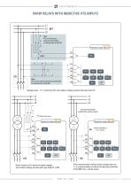
NV10P RELAYS WITH INDUCTIVE VTS INPUTS L1 L2 L3 A Note: VTs can be placed upstream (preferably) or downstream of the DDI Note: VTs can be placed upstream (preferably) or downstream of the DDI Voltage inputs - “V” connections VTs and residual voltage acquired with open delta VT restrictive thresholds enabled from external signal (*) Antiferrorisonance NV10P PROTECTION RELAY binary input set as f<-f> control DDI Direct measure of LV phase-to-phase voltages and residual voltage acquired with open delta VT in MV Direct measurement of phase-phase voltage input and f <-f> control enable by contact...
Open the catalog to page 3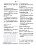
— Measuring inputs for inductive VTs or direct connection • Three phase-to-phase voltage inputs (UR = 100 V) or 200...520 V (UR = 400 V) from n. 2 VTs for NV10P-J... versions or LV direct connection for NV10P-U...versions) • One residual voltage input (connected on the secondary staropen delta VT). • Three phase-to-phase voltages U12, U23, U31 • Residual voltage UE • Average value of 3-phase voltages on 10 minutes with updates every three seconds • Frequency f (measured on phase-to-phase voltages) • Positive sequence voltage U1 (measured on phase-to-phase voltages) U1=(UL1+e+j120°·UL2+e-j120°·UL3)/3...
Open the catalog to page 4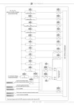
U E (residual voltage measured directly) Consenso f<-f> Consenso f<-f> P r esen za Goo se IN 1tOFF restrictive thresholds enabled for loss of communication network IN 1tOFF 0 T TRIPPING M ATRIX (LED+REL AYS) restrictive enabling thresholds from starting 59N external contact t UE>>def Binary input connected to remote trip external contact remote trip (Goose IEC61850) Functional diagram for the NV10P protection interface with inductive VTs NV10P - Fly
Open the catalog to page 5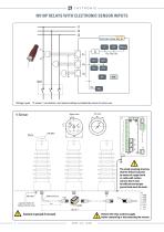
NV10P RELAYS WITH ELECTRONIC SENSOR INPUTS L1 L2 L3 Voltage inputs - “V-sensor” connections and residual voltage calculated by means of vector sum The metal mounting structure shall be linked to ground by means of copper braid or cable with section not less than 4 mm2. An efficient and unique ground node must be made. capacitive divider for voltage-indicator lamps Connect to ground if not used 6 Remove the relay auxiliary supply before connecting or disconnecting the sensors NV10P - Flyer -
Open the catalog to page 6
— Measuring inputs for electronic sensors connection Three phase-to-ground voltage inputs for V-Sensor or ThySensor. • Residual voltage UEC (calculated) UEC =|UL1+UL2 +UL3| • Average value of 3-phase voltages on 10 minutes with updates every three seconds • Frequency f (measured on phase-to-phase voltages) • Positive sequence voltage U1 (measured on phase-to-ground voltages) U1=(UL1+e+j120°·UL2+e-j120°·UL3)/3 where e-j120°=-1/2-j√3/2, ej120°=-1/2+j√3/2. • Negative sequence voltage U2 (measured on phase-to-ground voltages) U2 =(UL1+e-j120°·UL2+e+j120°·UL3)/3 where e-j120°=-1/2-j√3/2, ej120°=-1/2+j√3/2....
Open the catalog to page 7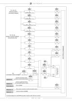
UL1, UL2, UL3 (phase-to-ground voltages measured directly) U EC (calculated residual voltage) Consenso f<-f> Consenso f<-f> P r esen za Goo se restrictive enabling thresholds from starting 59N external contact t UE>>def Binary input connected to remote trip external contact Remote trip (Goose IEC61850) Functional diagram for the NV10P protection interface with electronic sensors 8 IN 1tOFF restrictive thresholds enabled for loss of communication network TRIPPING M ATRIX (LED+REL AYS)
Open the catalog to page 8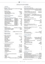
SPECIF ICAT IONS GENERAL INPUT CIRCUITS — Mechanical data Mounting: flush, projecting, rack or separated operator panel Mass (flush mounting case) 2.0 kg — Insulation tests Reference standards High voltage test 50Hz Impulse voltage withstand (1.2/50 ms) Insulation resistance — Voltage dip and interruption Reference standards — EMC tests for interference immunity 1 MHz damped oscillatory wave Electrostatic discharge Fast transient burst (5/50 ns) Conducted radio-frequency fields Radiated radio-frequency fields High energy pulse Magnetic field 50 Hz Damped oscillatory wave Ring wave Conducted common...
Open the catalog to page 9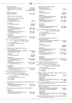
— Binary input timers ON delay time (IN1 tON, IN2 tON) 0.00...100.0 s OFF delay time (IN1 tOFF, IN2 tOFF) 0.00...100.0 s Logic Active-ON/Active-OFF — Relay output timers Minimum pulse width PROTECTIVE FUNCTIONS — Undervoltage - 27 (inductive VTs) Common configuration: • 27 Operating logic (Logic27) AND/OR U< Element • U< Curve type (U Element • U> Curve type (U>Curve) DEFINITE INVERSE [1] Definite time • 59 First threshold definite time (U >def) 0.50...1.50 U n • U>def Operating time (t U> def ) 0.03...100.0 s Inverse time • 59 First threshold inverse time (U >inv) 0.50...1.50 U n • U>inv Operating...
Open the catalog to page 10All THYTRONIC catalogs and technical brochures
 NA016
NA0168 Pages
 iRTUe
iRTUe4 Pages
 iRTU
iRTU4 Pages
 NA10
NA108 Pages
 NVA100X
20 Pages
 PRO-N
PRO-N16 Pages
 TIS
TIS1 Page
 TEST BLOCK SYSTEM - Flyer
8 Pages
 DCL-flyer
8 Pages
 NC020-Flyer
8 Pages
 NA011-Flyer
8 Pages
 Pro N - brochure
12 Pages
 brochure Serie S
4 Pages


Archived catalogs
 Product Flayer
4 Pages
- Current protection relay
- Digital protection relay
- Voltage protection relay
- Electric motor protection relay
- IEC protection relay
- Programmable protection relay
- Panel-mount protection relay
- Overload relay
- Over-current protection relay
- Differential protection relay
- AC protection relay
- Adjustable protection relay
- Over-voltage protection relay
- Generator protection relay
- Under-voltage protection relay
- Time delay protection relay
- RS485 protection relay
- Automatic control panel
- Frequency protection relay