- Catalogs
- ThyssenKrupp Magnettechnik
- Spreading Magnets
- Products
- Catalogs
- News & Trends
- Exhibitions
Spreading Magnets
1 /8Pages

Spreading Magnets
1 /8Pages
Catalog excerpts

ThyssenKrupp Magnettechnik Spreading Magnets When piles of sheets of different thickness are unloaded, double sheets could occur despite the use of spreading magnets (fanners), and this all the more, the thinner the sheets. The effects of a spreading magnet -either according to the electromagnetic or the permanentmagnetic principle- are based on a magnetic flux admitted to the sheet so that magnetic poles of the same kind are generated in the sheet which then repel in the same way as two magnetic north or south poles would do. This repulsion effect isolates two sheets lying directly upon each other. This is especially required if the blanks were oiled before and have been under pressure for some time with the sheets showing a strong sticky effect. This cannot be avoided in the usual processes, because the sheets must be protected against corrosion until the following process stage begins. As a general principle two different kinds of spreading magnets are differentiated: The purely permanentmagnetic electromagnetic one. 1. Permanentmagnetic Spreaders ( Fanners ) As the name already indicates, this kind of spreaders only consists of permanent magnets. The front view can be seen in figure 1 and has the following arrangement: iron plate Figure 1: Typical outline of a permanentmagnetic fanner The outline of the fanners can be seen. It represents an iron plate with permanent magnets sticking to them with the polarity specified; ‘north’ designates the north pole of the magnet which should be homogeneous on the complete area; ‘south’ designates the south pole of the other magnet. The sheet should stand perpendicularly on this area. The area of the magnets is covering about 90% of the working area. Johanniskirchstraße 71 45329 Essen, Germany Tel. +49 (0)201 946161-0 Fax +49 (0)201 946161-555
Open the catalog to page 1
ThyssenKrupp Magnettechnik 2. Electromagnetic Spreaders ( Fanners ) In case of electromagnetic spreaders the magnetic flux is not generated by permanent magnets, but by coils (solenoids). Depending on the arrangement (two- pole or three- pole) two or three coils are applied. The kind of operation is the same as with permanentmagnetic spreaders, however with some restrictions to be explained below. But first of all a principle drawing in figure 2: iron plate iron pole The pole area of the iron poles covers only about 20% up to 30% of the working area Figure 2: Typical outline of a conventional,...
Open the catalog to page 2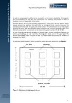
ThyssenKrupp Magnettechnik In order to compensate this effect as far as possible, a iron strip is attached to the magnetic pole surrounded by the coil; this strip exceeds the end windings and extends the lines of magnetic flux to the lower edge of the system. A further effect of the reduced spreading performance is to be seen in the fact that the sheets already lying on the pile have the same effect as a magnetic short- circuit and reduce the spreading performance in the upper part of the system. This phenomenon can be reduced by grooving the centre pole; thus the effect of the magnetic short-...
Open the catalog to page 3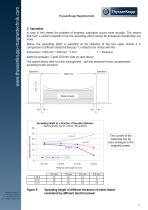
ThyssenKrupp Magnettechnik 3. Saturation In case of thin sheets the problem of magnetic saturation occurs more strongly. This means that from a certain magnetic force the spreading effect cannot be increased considerably any more. Below, the spreading effect is specified as the distance of the two upper sheets a in comparison to different sheet thicknesses T, related to the sheets with the dimensions: 1000 mm * 300 mm * T mm electrical spreader, 3-pole 220 mm wide as seen above. The specifications refer to a test arrangement - with the attractive forces compensated according to the structure:...
Open the catalog to page 4
ThyssenKrupp Magnettechnik Figure 5 shows the dependence of the sheet thickness. It can be seen that considerable difference as to the spreading height cannot be detected with a sheet being 0.5mm thick. The differences are not considerable up to sheets being 1.0 mm thick, since it is only 1 mm with the coil current being constant. In practice this should hardly be noticeable. In case of sheets being 2 or 3 mm thick the differences become noticeable. In case of a coil current of 2.5 A it can be noticed that the spreading height increases when the thickness of the sheet increases as well. This...
Open the catalog to page 5
ThyssenKrupp Magnettechnik 5. Edge Covering Furthermore the spreading height depends on the edge covering. That is the width of all spreaders applied to the sheet bundle in relation to the circumference of a sheet resp. the ratio in percent of system edge length and sheet edge length. Normally the spot where the spreading magnet is in contact with the sheet is the point where this sheet is magnetically saturated. This means that the spreading height can only be increased by increasing the number of spreading magnets applied so that the edge covering is increased as well. In order to be capable...
Open the catalog to page 6
ThyssenKrupp Magnettechnik 7. Coil Design of the optimized fanner mentioned above The max. conduction theta in A can be derived from the fieldnumeric calculation; it results in turn in the determination of the concrete coil data with the connected voltage specified: example: conduction theta Θ = 2200 A for each solenoid cross- sectional area of the coil space: 1200 mm2 first of all one single turn is assumed, so that I = Θ U’ = R * I = Ro * (Lm/A) * (Θ / Fc) with Fc =copper bulk factor and Ro = specific resistance of Cu Lm = mean turn length and A = cross section area = 0.0175 mm * Ohm/m * (0.266...
Open the catalog to page 7
ThyssenKrupp Magnettechnik 9. Different possibilities of positioning the spreading magnets Due to the free space there exist different possibilities of positioning of the spreading magnets; these will be shown in the following figure 6. The attractive force of the magnets can be used to allocate a supplementary centering function: single sided arrangement centering arrangement at one edge symmetric arrangement centering arrangement Examples of different arrangements of spreading magnets
Open the catalog to page 8All ThyssenKrupp Magnettechnik catalogs and technical brochures
 Filter magnets
2 Pages
 Magnetic sheet separators
3 Pages
 Pot magnets
8 Pages
 Hard ferrite magnets
4 Pages
 Magnets move us
9 Pages
 holding magnets
40 Pages
 AlNiCo-Magnets
40 Pages


- Solids separator
- Liquids separator
- Eddy current separator
- Lifting magnet
- Neodymium magnet
- Separator for the food industry
- Cylindrical magnet
- Coated magnet
- Rectangular magnet
- Permanent lifting magnet
- Holding magnet
- Manually switched permanent lifting magnet
- Ferrite magnet
- Ring magnet
- Handling permanent lifting magnet
- Gaussmeter
- Samarium-cobalt magnet
- Disc magnet
- Destacker
- AlNiCo permanent magnet