- Products
- Catalogs
- News & Trends
- Exhibitions
SCR
1 /8Pages
SCR
1 /8Pages
Catalog excerpts

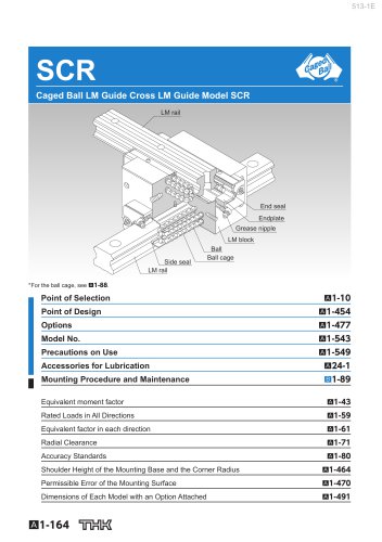
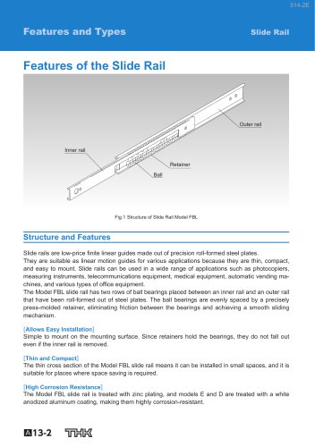
SCR Caged Ball LM Guide Cross LM Guide Model SCR LM rail End seal Endplate Grease nipple LM block Side seal LM rail Ball Ball cage Mounting Procedure and Maintenance Equivalent moment factor Rated Loads in All Directions Equivalent factor in each direction Radial Clearance Accuracy Standards Shoulder Height of the Mounting Base and the Corner Radius Permissible Error of the Mounting Surface Dimensions of Each Model with an Option Attached
Open the catalog to page 1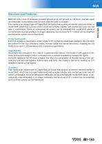
[4-way Equal Load] Each row of balls is placed at a contact angle of 45 so that the rated loads applied to the LM block are uniform in the four directions (radial, reverse radial and lateral directions), enabling the LM Guide to be used in all orientations and in extensive applications. [High Rigidity] Since balls are arranged in four rows in a well-balanced manner, this model is stiff against a moment, and smooth straight motion is ensured even a preload is applied to increase the rigidity. Since the rigidity of the LM block is higher than that of a combination of two LM blocks of the conventional...
Open the catalog to page 2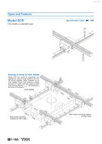
This model is a standard type. Drawing of Using an Inner Saddle Model SCR can easily be assembled and adjusted by using an inner saddle to link four LM blocks together. When installed on an inner saddle, model SCR achieves a highly accurate X-Y guide and high rigidity moment in the yawing direction (as indicated by the arrow in the figure). Inner saddle Ball screw mounting location on the Y axis Ball screw mounting location on the X axi
Open the catalog to page 3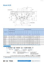
Outer dimensions Model No. Height Width Length M Model number coding 4 SCR25 QZ KKHH C0 +1200/1000L P Model number Contamination protection accessory symbol (*1) LM rail length on the X axis (in mm) LM rail length on the Y axis (in mm) Radial clearance symbol (*2) Normal (No symbol)/Light preload (C1) Medium preload (C0) Accuracy symbol (*3) Precision grade (P) Super precision grade (SP) Ultra precision grade (UP) (*1) See contamination protection accessory on A1-516. (*2) See A1-71. (*3) See A1-80. Note) Those models equipped with QZ Lubricator cannot have a grease nipple. When desiring a grease...
Open the catalog to page 5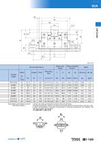
Basic load rating LM rail dimensions Width Grease nipple Static permissible moment* Mounting hole Note) Static permissible moment* 1 block: the static permissible moment with one LM block Total block length L : The total block length L shown in the table is the length with the dust proof parts, code UU or SS. If other contamination protection accessories or lubricant equipment are installed, the total block length will increase. (See A1-491
Open the catalog to page 6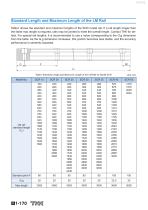
Standard Length and Maximum Length of the LM Rail Table1 shows the standard and maximum lengths of the SCR model rail. If a rail length longer than the listed max length is required, rails may be jointed to meet the overall length. Contact THK for details. For special rail lengths, it is recommended to use a value corresponding to the G,g dimension from the table. As the G,g dimension increases, this portion becomes less stable, and the accuracy performance is severely impacted. F L0 Table1 Standard Length and Maximum Length of the LM Rail for Model SCR LM rail standard length (L0)
Open the catalog to page 7
SCR Tapped-hole LM Rail Type of Model SCR The model SCR variations include a type with its LM rail bottom tapped. With the X-axis LM rail having tapped holes, this model can be secured with bolts from the top. Table2 Dimensions of the LM Rail Tap Unit: mm Model number coding 4 SCR35 KKHH C0 +1000/1000L P K Symbol for tapped-hole LM rail type Tapped-hole rail
Open the catalog to page 8All THK catalogs and technical brochures
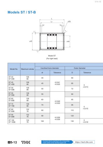 Models ST / ST-B
2 Pages
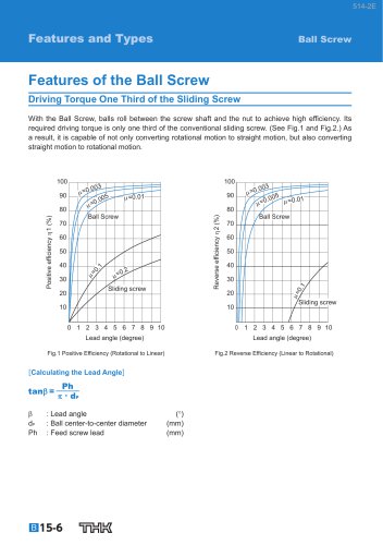
 Predicting the Rigidity
5 Pages
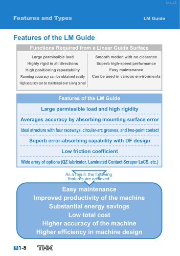 Features of the LM Guide
16 Pages
 PCT/PC
40 Pages
 Models SHS-C and SHS-LC
2 Pages
 Models SSR-XW and SSR-XWM
2 Pages
 Models SSR-XV and SSR-XVM
2 Pages
 LM ACTUATOR GL
20 Pages
 HDR
HDR28 Pages
 RSX
RSX6 Pages
 Fix Stages
4 Pages
 Finite Stroke LM Guide EPF
12 Pages
 LM ACTUATOR GL-N
28 Pages
 LM Actuator TY
16 Pages
 Clean-Room Actuator Model CSKR
20 Pages


Archived catalogs
 Model SSR-XTB
2 Pages
 Catalogue Caged Ball LM Guide
23 Pages
 Low Price Actuator Model VLA
16 Pages
 LM Guide Actuator Model KR
92 Pages
 Ball Spline Series
24 Pages
 Cross-Roller Ring Series
28 Pages
 High-temparature LM Guide Series
28 Pages
 Model HR Separate Type
20 Pages
 LM Actuator Model TY
16 Pages
 Guide Ball Bush LG
8 Pages
 Limited-stroke LM Guide
12 Pages
 LM Actuator Model GL-N
28 Pages
 RoD Actuato
12 Pages
 Product Ordering Guide
8 Pages
 LM Guide Actuator KR
68 Pages


- Nut
- Metal nut
- THK linear guide
- Metal stand
- Plain bearing
- Bearing unit
- Metal plain bearing
- Telescopic slide
- Slewing bearing
- Steel linear guide
- THK ball bearing linear guide
- Rod end
- Metal bushing
- Slide carriage block
- Cantilever axis
- THK compact linear guide
- Single-row slewing ring
- THK precision linear guide
- Roller slide