- Products
- Catalogs
- News & Trends
- Exhibitions
Rotary Ball Spline With Support Bearing Type Models LTR and LTR-A
1 /11Pages

Rotary Ball Spline With Support Bearing Type Models LTR and LTR-A
1 /11Pages
Catalog excerpts
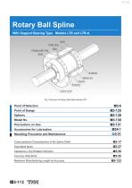
Rotary Ball Spline With Support Bearing Type Models LTR and LTR-A Seal Outer ring Flange outer ring Retainer Spline nut Spacer Retainer Spline shaft Fig.1 Structure of Rotary Ball Spline Model LTR Mounting Procedure and Maintenance Cross-sectional Characteristics of the Spline Shaft Equivalent factor Clearance in the Rotation Direction Accuracy Standards Maximum Manufacturing Length by Accuracy
Open the catalog to page 1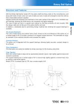
Rotary Ball Spline Structure and Features [No Angular Backlash] Two rows of balls facing one another hold a crest, formed on the circumference of the spline nut, at a contact angle of 20 to provide a preload in an angular-contact structure. This eliminates an angular backlash in the rotational direction and increases the rigidity. [Compact Design] The spline nut is integrated with the support bearings, allowing highly accurate, compact design to be achieved. [Easy Installation] This ball spline can easily be installed by simply securing it to the housing using bolts. [High Rigidity] Since the...
Open the catalog to page 2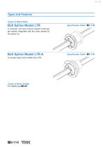
Types and Features [Types of Spline Nuts] Ball Spline Model LTR A compact unit type whose support bearings are directly integrated with the outer surface of the spline nut. Ball Spline Model LTR-A A compact type even smaller than LTR. [Types of Spline Shafts] For details,see A3-81. Specification Table⇒A
Open the catalog to page 3
Rotary Ball Spline Housing Inner-diameter Tolerance For the housing inner-diameter tolerance for model LTR, class H7 is recommended. [Important note concerning model LTR] Flange Outer ring Note) Because of the divided outer ring, it is necessary to incorporate inner-diameter tolerance in the nut bracket (H7 is recommended) to prevent shifting of the outer ring on the side opposite the flange. Ball Spline Pulley Outer ring
Open the catalog to page 4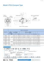
Model LTR-A Compact Type Standard type L1 Type K (Inverted flange) E F Spline nut dimensions Model No. Outer diameter TolerD ance 32 Flange diameter Standard Oil hole Type K type position Model number coding Flange orientation Compact Support Type Accuracy symbol symbol(*1) (*5) Symbol for spline shaft (*6) Spline nut contamination Symbol for clearance protection accessory in the rotational direction(*4) symbol(*2) Number of spline nuts Support bearings Overall spline shaft length (*7) on one shaft contamination protection (in mm) (no symbol for one nut) accessory symbol(*3) Download data by...
Open the catalog to page 5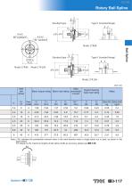
Rotary Ball Spline L E L1 H Standard type Type K (Inverted flange) E F Ball Spline Standard type Type K (Inverted flange) E F Spline shaft diameter Static Basic torque rating Basic load rating permissible moment Support bearing basic load rating Spline Nut Spline shaft kg kg/m 0.08 Note) **MA indicates the permissible moment value in the axial direction when a single spline nut is used, as shown in the figure below. For details on the maximum lengths of ball spline shafts by accuracy, please see A3-123.
Open the catalog to page 6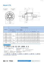
Spline nut dimensions Model No. Flange diameter Model number coding 2 LTR50 K UU ZZ CM +1000L H K Model No. Flange orientation symbol(*1) Symbol for clearance Accuracy symbol in the rotational (*5) direction(*4) Symbol for spline shaft (*6) Number of spline nuts Spline nut Support bearings Overall spline shaft length (*7) on one shaft contamination protection contamination protection (in mm) accessory symbol(*3) (no symbol for one nut) accessory symbol(*2) Download data by searching for the corresponding model number on the Technical Support si
Open the catalog to page 7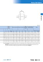
Rotary Ball Spline Ball Spline Unit: mm Spline shaft diameter Static Basic torque rating Basic load rating permissible moment Support bearing basic load rating Spline Nut Spline shaft kg kg/m MA indicates the permissible moment value in the axial direction when a single spline nut is used, as shown in the figure above. Dimension U represents the dimension from the head of the hexagonal-socket-head type bolt to the spline nut end. For details on the maximum lengths of ball spline shafts by accuracy, please see A3-123.
Open the catalog to page 8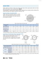
Spline Shaft Spline shafts are divided in shape into precision solid spline shaft, special spline shaft and hollow spline shaft (types K and N), as described on A3-81. Since production of a spline shaft with a specific shape is performed at your request, provide a drawing of the desired shaft shape when asking an estimate or placing an order. [Sectional Shape of the Spline Shaft] Table1 shows the sectional shape of a spline shaft. If the spline shaft ends need to be cylindrical, the minor diameter ( d) value should not be exceeded if possible. Table1 Sectional Shape of the Spline Shaft Nominal...
Open the catalog to page 9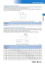
Rotary Ball Spline [Chamfering of the Spline Shaft Ends] To facilitate the insertion of the spline shaft into a spline nut, the shaft ends are normally chamfered with the dimensions indicated below unless otherwise specified. The ends are chamfered whether they are used, such as with stepped, tapped, or drilled ends, or not used, such as with cantilevered supports. C [Length of Incomplete Area of a Special Spline Shaft] If the middle area or the end of a spline shaft is to be thicker than the minor diameter ( d), an imperfect spline area is required to secure a recess for grinding. Table4 shows...
Open the catalog to page 10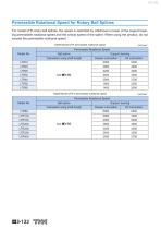
Permissible Rotational Speed for Rotary Ball Splines For model LTR rotary ball splines, the speed is restricted by whichever is lower of the support bearing permissible rotational speed and the critical speed of the spline. When using the product, do not exceed the permissible rotational speed. Table5 Model LTR permissible rotational speed Permissible Rotational Speed Model No. Ball spline Support bearing Calculated using shaft length Grease Lubrication Table6 Model LTR-A permissible rotational speed Permissible Rotational Speed Model No. Ball spline Calculated using shaft length Support bearing...
Open the catalog to page 11All THK catalogs and technical brochures
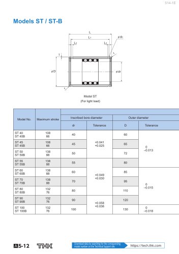 Models ST / ST-B
2 Pages
 Predicting the Rigidity
5 Pages
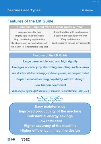 Features of the LM Guide
16 Pages
 PCT/PC
40 Pages
 Models SHS-C and SHS-LC
2 Pages
 Models SSR-XW and SSR-XWM
2 Pages
 Models SSR-XV and SSR-XVM
2 Pages
 SCR
SCR8 Pages
 LM ACTUATOR GL
20 Pages
 HDR
HDR28 Pages
 RSX
RSX6 Pages
 Fix Stages
4 Pages
 Finite Stroke LM Guide EPF
12 Pages
 LM ACTUATOR GL-N
28 Pages
 LM Actuator TY
16 Pages
 Clean-Room Actuator Model CSKR
20 Pages


Archived catalogs
 Model SSR-XTB
2 Pages
 Catalogue Caged Ball LM Guide
23 Pages
 Low Price Actuator Model VLA
16 Pages
 LM Guide Actuator Model KR
92 Pages
 Ball Spline Series
24 Pages
 Cross-Roller Ring Series
28 Pages
 High-temparature LM Guide Series
28 Pages
 Model HR Separate Type
20 Pages
 LM Actuator Model TY
16 Pages
 Guide Ball Bush LG
8 Pages
 Limited-stroke LM Guide
12 Pages
 LM Actuator Model GL-N
28 Pages
 RoD Actuato
12 Pages
 Product Ordering Guide
8 Pages
 LM Guide Actuator KR
68 Pages


- Metal nut
- THK linear guide
- Metal stand
- Plain bearing
- Bearing unit
- Metal plain bearing
- Telescopic slide
- Slewing bearing
- Steel linear guide
- THK ball bearing linear guide
- Rod end
- Metal bushing
- Ball screw
- Slide carriage block
- Cantilever axis
- THK compact linear guide
- Single-row slewing ring
- THK precision linear guide
- Roller slide