- Products
- Catalogs
- News & Trends
- Exhibitions
Rotary Ball Spline With Geared Type Models LBG and LBGT
1 /12Pages

Rotary Ball Spline With Geared Type Models LBG and LBGT
1 /12Pages
Catalog excerpts

Rotary Ball Spline Geared Type Models LBG and LBGT Spline shaft Gear Outer ring Thrust bearings Radial bearings Fig.1 Structure of Rotary Ball Spline Model LBG Mounting Procedure and Maintenance Cross-sectional Characteristics of the Spline Shaft Equivalent factor Clearance in the Rotation Direction Accuracy Standards Maximum Manufacturing Length by Accuracy
Open the catalog to page 1
Rotary Ball Spline Structure and Features With the Rotary Ball Spline, the spline shaft has three crests, and along both sides of each crest, two rows of balls (six rows in total) are arranged to hold the crest so that a reasonable preload is applied. These models are unit types based on model LBR, but have gear teeth on the flange circumference and radial and thrust bearings on the spline nut, all compactly integrated. The rows of balls are held in a special resin retainer so that they smoothly roll and circulate. With this design, balls will not fall even if the spline shaft is removed. [Compact...
Open the catalog to page 2
Types and Features [Types of Spline Nuts] Ball Spline with Gears Model LBG These models are unit types based on model LBR, but have gear teeth on the flange circumference and radial and thrust bearings on the spline nut, all compactly integrated. It is optimal for a torque transmission mechanism with spline nut drive. Without a thrust raceway Ball Spline with Gears Model LBGT These models are unit types based on model LBR, but have gear teeth on the flange circumference and radial and thrust bearings on the spline nut, all compactly integrated. It is optimal for a torque transmission mechanism...
Open the catalog to page 3
Rotary Ball Spline Housing Inner-diameter Tolerance Table1 shows housing inner-diameter tolerance for models LBG and LBGT. Table1 Housing Inner-diameter Tolerance Housing Inner-diameter Tolerance General conditions When clearance needs to be small Ball Spline
Open the catalog to page 4
Spline nut dimensions Model No. Spline nut outer diameter D Outer diameter Note) ●: indicates model numbers for which felt seal types are available (see A3-126). Model number coding 2 LBG50 UU CM +700L H K Symbol for clearance Accuracy symbol in the rotational direction (*3) (*2) Symbol for spline shaft (*4) Number of spline nuts on one shaft (no symbol for one nut) Contamination protection Overall spline shaft length (*5) accessory symbol (in mm) (*1) Download data by searching for the corresponding model number on the Technica
Open the catalog to page 5
Rotary Ball Spline Ball Spline Unit: mm Static Basic torque rating Basic load rating permissible moment Gear specifications* Tip circle Standard pitch diameter diameter PCD D5 Note) The gear specifications in the table represent the dimensions with maximum module. Special gear types such as helical gear and worm gear can also be manufactured at your request. ** MA indicates the permissible moment value in the axial direction when a single spline nut is used, as shown in the figure above. For details on the maximum lengths of ball spline shafts by accuracy, please see A3-121. *
Open the catalog to page 6
Spline nut dimensions Model No. Spline nut outer diameter D Outer diameter Thrust raceway width Note) ●: indicates model numbers for which felt seal types are available (see A3-126). Model number coding Symbol for clearance Accuracy symbol in the rotational direction (*3) (*2) Symbol for spline shaft (*4) Number of spline nuts Contamination protection Overall spline shaft length (*5) accessory symbol on one shaft (in mm) (no symbol for one nut) (*1) Download data by searching for the corresponding model number on the Technica
Open the catalog to page 7
Rotary Ball Spline Ball Spline Unit: mm Static Basic torque rating Basic load rating permissible moment Gear specifications* Tip circle Standard pitch diameter diameter D5 PCD Note) The gear specifications in the table represent the dimensions with maximum module. Special gear types such as helical gear and worm gear can also be manufactured at your request. ** MA indicates the permissible moment value in the axial direction when a single spline nut is used, as shown in the figure above. For details on the maximum lengths of ball spline shafts by accuracy, please see A3-121. *
Open the catalog to page 8
Spline Shaft Spline shafts are divided in shape into precision solid spline shaft, special spline shaft and hollow spline shaft (type K), as described on A3-57. Since production of a spline shaft with a specific shape is performed at your request, provide a drawing of the desired shaft shape when asking an estimate or placing an order. [Sectional Shape of the Spline Shaft] Table2 shows the sectional shape of a spline shaft. If the spline shaft ends need to be cylindrical, the minor diameter ( d) value should not be exceeded if possible. Table2 Sectional Shape of the Spline Shaft Nominal shaft...
Open the catalog to page 9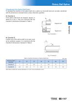
Rotary Ball Spline [Chamfering of the Spline Shaft Ends] To facilitate the insertion of the spline shaft into a spline nut, the shaft ends are normally chamfered with the dimensions indicated below unless otherwise specified. Chamfer A If the spline shaft ends are stepped, tapped, or drilled as in Fig. 2, they are machined with the Chamfer A dimensions indicated in Table 4. Ball Spline Chamfer B If either end of the spline shaft is not used, such as for cantilever support, it is machined with the Chamfer B dimensions indicated in Table 4. Table 4 Chamfer Dimensions of Spline Shaft Ends Nominal...
Open the catalog to page 10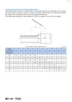
[Length of Imperfect Area of a Special Spline Shaft] If the middle area or the end of a spline shaft is to be thicker than the minor diameter ( d), an imperfect spline area is required to secure a recess for grinding. Table5 shows the relationship between the length of the incomplete section (S) and the flange diameter ( df). (This table does not apply to overall length of 1,500 mm or greater. Contact THK for details.) Gr Table5 Length of Imperfect Spline Area: S
Open the catalog to page 11
Rotary Ball Spline Ball Spline
Open the catalog to page 12All THK catalogs and technical brochures
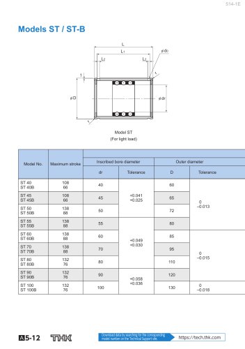 Models ST / ST-B
2 Pages
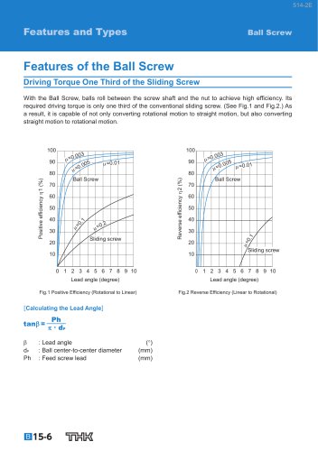
 Predicting the Rigidity
5 Pages
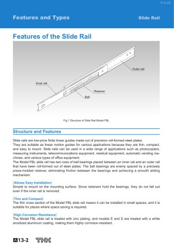
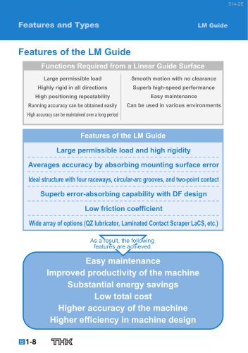 Features of the LM Guide
16 Pages
 PCT/PC
40 Pages
 Models SHS-C and SHS-LC
2 Pages
 Models SSR-XW and SSR-XWM
2 Pages
 Models SSR-XV and SSR-XVM
2 Pages
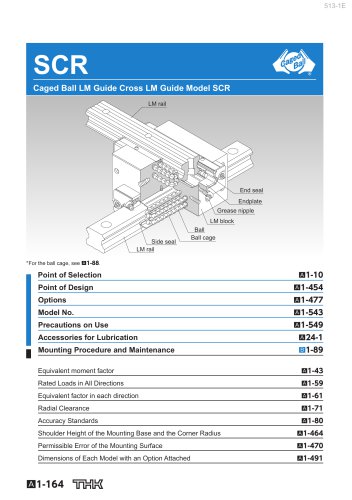 SCR
SCR8 Pages
 LM ACTUATOR GL
20 Pages
 HDR
HDR28 Pages
 RSX
RSX6 Pages
 Fix Stages
4 Pages
 Finite Stroke LM Guide EPF
12 Pages
 LM ACTUATOR GL-N
28 Pages
 LM Actuator TY
16 Pages
 Clean-Room Actuator Model CSKR
20 Pages


Archived catalogs
 Model SSR-XTB
2 Pages
 Catalogue Caged Ball LM Guide
23 Pages
 Low Price Actuator Model VLA
16 Pages
 LM Guide Actuator Model KR
92 Pages
 Ball Spline Series
24 Pages
 Cross-Roller Ring Series
28 Pages
 High-temparature LM Guide Series
28 Pages
 Model HR Separate Type
20 Pages
 LM Actuator Model TY
16 Pages
 Guide Ball Bush LG
8 Pages
 Limited-stroke LM Guide
12 Pages
 LM Actuator Model GL-N
28 Pages
 RoD Actuato
12 Pages
 Product Ordering Guide
8 Pages
 LM Guide Actuator KR
68 Pages


- Metal nut
- THK linear guide
- Metal stand
- Plain bearing
- Bearing unit
- Metal plain bearing
- Telescopic slide
- Slewing bearing
- Steel linear guide
- THK ball bearing linear guide
- Rod end
- Metal bushing
- Ball screw
- Slide carriage block
- Cantilever axis
- THK compact linear guide
- Single-row slewing ring
- THK precision linear guide
- Roller slide