Catalog excerpts

TOKYO. JAPAN
Open the catalog to page 1
Separate Type Cross section Balls roll in two rows of raceways precision-ground on an LM rail and an LM block, and endplates incorporated in the LM block allow the balls to circulate. Since retainer plates hold the balls, they do Because of the angular contact structure where two rows of balls rolling on the LM rail each contact the raceway at 45°, the same load can be applied in four directions (radial, reverse-radial and lateral directions) if a set of model HR components is mounted on the same plane (i.e., when two LM rails are combined with LM blocks on the same plane). Furthermore,...
Open the catalog to page 2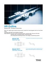
Model HR - Product Overview With a thin, highly rigid and space saving structure, model HR is interchangeable with the Cross Roller A stainless steel type is also available as standard. I Major applications IXYZ axes of electric discharge machine / precision table / XZ axes of NC lathe / assembly robot/conveyance system / machining center/ wire-cutting electric discharge machine / tool changer / woodworking machine Heavy-load Type The LM blocks can be mounted from the top and the bottom. Ultra-heavy Load Type It has the same sectional shape as model HR, but has a greater overall LM block...
Open the catalog to page 3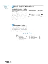
Q Rated Loads in All Directions When installed, one set of model HR is capable of receiving loads in all four directions: radial, reverse-radial and lateral directions. The basic load ratings of an installed set of model HR are equal in all four directions (ra- dial, reverse-radial and lateral directions). The basic load ratings in the dimensional table*1 for model HR indicate the values in the radial direction per LM block as shown in the Reverse-radial direction Radial direction When the LM block of model HR receives loads in the reverse-radial and lateral directions simultaneously, the...
Open the catalog to page 4
Model HR - Product Overview QService life The service life of an LM Guide is subject to variations even under the same operational conditions. Therefore, it is necessary to use the rated life defined below as a reference value for obtaining the service life of the LM Guide. •Rated life The rated life means the total travel distance that 90% of a group of units of the same LM Guide model can achieve without flaking (scale-like exfoliation on the metal surface) after individually running under the same •Service life time Once the rated life (L) has been obtained, the service life time can be...
Open the catalog to page 5
O Example of Clearance Adjustment Design the clearance adjustment screw so that it presses the center of the side face Using a clearance screw Normally, press the LM block with an adjusting screw. Using tapered gibs When high accuracy and high rigidity are required, use tapered gibs 1) and 2). THK manufactures a type whose clear- ances are adjusted with an eccentric pin.
Open the catalog to page 6
Model HR - Product Overview The accuracy of model HR is specified in terms of running parallelism (*1), dimensional tolerance for height and width, and height and width difference between a pair f2 *3) when two or more LM blocks are used on one rail or when two or more rails are mounted on the same plane. The accuracy of model HR is defined by model numbers as indicated in the table below. Difference in height M applies to a set of model HR components used on the same plane. Difference In total width Wo applies to LM blocks used In combination on one LM rail. Dimensional tolerance and...
Open the catalog to page 7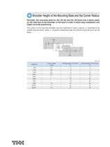
O Shoulder Height of the Mounting Base and the Corner Radius Normally, the mounting base for the LM rail and the LM block has a datum plane on the side face of the shoulder of the base in order to allow easy installation and highly accurate positioning. The corner of the mounting shoulder must be machined to have a recess, or machined to be smaller than the corner radius "r," to prevent interference with the chamfer of the LM rail or the LM
Open the catalog to page 8
Model HR - Product Overview 9 Error Allowance in the Parallelism Between Two Rails The following table shows error allowances in parallelism (P) between two rails that will not affect the service life in normal operation. Q Error Allowance in Vertical Level Between Two Rails The values in the table each indicate the error —|—r±i-ri!—|—rtr allowances in vertical level between two rails I.I j I.I_I.I i I.I are proportional to the axis-to-axis distances. I_ \i _I I_ ]"•' _I s
Open the catalog to page 9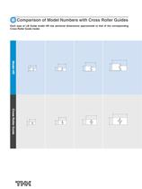
^Comparison of Model Numbers with Cross Roller Guides Each type of LM Guide model HR has sectional dimensions approximate to that of the corresponding Cross Roller Guide model.
Open the catalog to page 10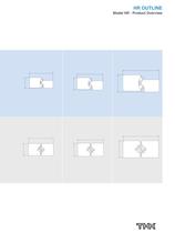
Model HR - Product Overview
Open the catalog to page 11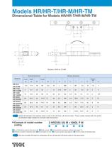
Models HR/HR-T/HR-M/HR-TM Dimensional Table for Models HR/HR-T/HR-M/HR-TM Symbol M indicates that stainless steel is used in the LM block, LM rail and balls. Those models marked with this symbol are therefore highly resistant to corrosion and environment. ■ Example of model number 2 HR2555 UU M +1000L P M ÖNo. of LM blocks used on the same rail HModel number HDust prevention accessory symbol (see page 17) HLM block is made of stainless steel 0LM rail length (in mm) HAccuracy symbol (see page 6) QLM rail is made of stainless steel One set of model HR means a combination of two LM rails and...
Open the catalog to page 12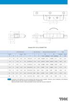
A moment in the direction Mo can be received if two rails are used in parallel. However, since it depends on the distance between the two rails, the moment in the direction Mo is omitted here. Static permissible moment*: Static permissible moment value with one set of model HR
Open the catalog to page 13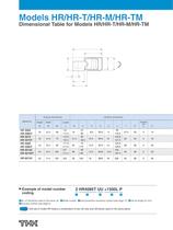
Models HR/HR-T/HR-M/HR-TM Dimensional Table for Models HR/HR-T/HR-M/HR-TM ■ Example of model number 2 HR4085T UU +1500L P ÖNo. of LM blocks used on the same rail HModel number HDust prevention accessory symbol (see page 17) HLM rail length (in mm) HAccuracy symbol (see page 6) One set of model HR means a combination of two LM rails and LM blocks used on the same plane.
Open the catalog to page 14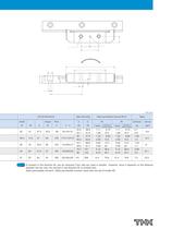
A moment in the direction Mo can be received if two rails are used in parallel. However, since it depends on the distance between the two rails, the moment in the direction Mo is omitted here. Static permissible moment*: Static permissible moment value with one set of model HR
Open the catalog to page 15All THK catalogs and technical brochures
-
Models ST / ST-B
2 Pages
-
Predicting the Rigidity
5 Pages
-
Features of the LM Guide
16 Pages
-
Features of the Slide Rail
1 Pages
-
PCT/PC
40 Pages
-
Models SHS-C and SHS-LC
2 Pages
-
Models SSR-XW and SSR-XWM
2 Pages
-
Models SSR-XV and SSR-XVM
2 Pages
-
SCR
8 Pages
-
LM ACTUATOR GL
20 Pages
-
HDR
28 Pages
-
RSX
6 Pages
-
Fix Stages
4 Pages
-
Finite Stroke LM Guide EPF
12 Pages
-
LM ACTUATOR GL-N
28 Pages
-
LM Actuator TY
16 Pages
-
Clean-Room Actuator Model CSKR
20 Pages
Archived catalogs
-
Model SSR-XTB
2 Pages
-
Catalogue Caged Ball LM Guide
23 Pages
-
Low Price Actuator Model VLA
16 Pages
-
LM Guide Actuator Model KR
92 Pages
-
Ball Spline Series
24 Pages
-
Cross-Roller Ring Series
28 Pages
-
High-temparature LM Guide Series
28 Pages
-
LM Actuator Model TY
16 Pages
-
Guide Ball Bush LG
8 Pages
-
Limited-stroke LM Guide
12 Pages
-
LM Actuator Model GL-N
28 Pages
-
RoD Actuato
12 Pages
-
Product Ordering Guide
8 Pages
-
LM Guide Actuator KR
68 Pages


