- Products
- Catalogs
- News & Trends
- Exhibitions
LM Guide Actuator Model KR
1 /92Pages

LM Guide Actuator Model KR
1 /92Pages
Catalog excerpts

LM Guide Actuator KR For details, visit THK at www.thk.com Product information is updated regularly on the THK website. CATALOG No.209-8E
Open the catalog to page 1
KR Precautions on Use Integrated LM Guide and Ball Screw High-rigidity / High-precision Actuator LM Guide Actuator Model KR Model No. KR15 to 65 Handling (1) Do not disassemble this product unless absolutely necessary. This will cause dust to enter the product resulting in loss of functionality. (2) Take care not to drop or strike this product. This could cause injury or product damage. Giving an impact to it could also cause damage to its function even if the product looks intact. (3) Exceeding the dangerous speed may lead the components to be damaged or cause an accident. Be sure to use the...
Open the catalog to page 2
• Load Ratings in All Directions and Static Permissible Moment.. 8 Example of Calculating the Nominal Life.. 20 Dimensional Drawing, Dimensional Table
Open the catalog to page 3
KR LM Guide Actuator Model KR LM Guide + Ball Screw = Integral-structure Actuator Stopper Housing B Ball screw Inner block Grease nipple Bearing (supported side) Outer rail Housing A Stopper Double-row ball circuit Bearing (fixed side) Fig.1 Structure of LM Guide Actuator Model KR Structure and Features Because of its integral-structure inner block consisting of a highly rigid outer rail with a U-shaped cross section, LM Guide units on both side faces and a Ball Screw unit in the center, LM Guide Actuator model KR achieves a highly rigid and highly accurate actuator in a minimal space. In addition,...
Open the catalog to page 4
Each row of balls is arranged at a contact angle of 45° so that the rated load on the inner block is uniform under loads applied to the inner block in the four directions (radial, reverse radial and lateral directions). As a result, model KR can be used in any mounting orientation. Fig.2 Load Capacity and Contact Angle of Model KR [High Rigidity] Use of an outer rail with a U-shaped cross sec- tion increases the rigidity against a moment and Fig.3 Cross Section of the Outer Rail [High Accuracy] Since the linear guide section consists of 4 rows of circular-arc grooves that enable balls to smoothly...
Open the catalog to page 5
Space Saving Use of a inner block integrating LM Guide units on both ends and a Ball Screw unit in the center makes model KR a highly rigid and highly accurate actuator in a minimal space. Model KR65 Model KR55 Model KR46 Model KR45H Model KR33 10mm Model KR30H Model KR15 Model KR20 Model KR26 10mm Fig.5 Cross Sectional Drawing 5
Open the catalog to page 6
Model KR is equipped with end seals and side seals for dust prevention as standard. Side seal Table2 shows the rolling resistance and seal resistance per inner block (guide section). Table2 Maximum Resistance Value Unit: N Note) The rolling resistance represents the value when a
Open the catalog to page 7
Model KR-B (with Two Long Type Blocks) Equipped with two units of the inner block of model KR-A, this model achieves higher rigidity and higher load carrying capacity. Model KR-C (with a Single Short Type Block) This model has a shorter overall length of the in- ner block and a longer stroke than model KR-A. Model KR-D (with Two Short Type Blocks) Equipped with two units of the inner block of model KR-C, this design allows a span between blocks that suits the equipment, thus to achieve high rigidity.
Open the catalog to page 8
Load Ratings in All Directions and Static Permissible Moment Model KR is capable of receiving loads in four directions (radial, reverse radial and lateral direc- tions). Its basic load ratings are equal in all four directions (radial, reverse radial and lateral direc- tions), and their values are indicated in Table3 on page9 and pagel 0. • Ball Screw Unit Since the inner block is incorporated with a ball screw nut, model KR is capable of receiving an axial load. The basic load rating value is indicated in Table3 on page9 and pagel 0. • Bearing Unit (Fixed Side) Since housing A contains an angular...
Open the catalog to page 9
Table3 Load Rating of Model KR Notel) The load ratings in the LM Guide unit each indicate the load rating per inner block. Note2) The Ball Screw of precision grade (grade P) for models KR30H, KR33, KR45H10 and KR4610 is incorporated with spacer balls in the proportion of one to one. Note3) The Ball Screw of precision grade (grade P) for models KR45H20, KR4620, KR55 and KR65 is incorporated with spacer
Open the catalog to page 10
[Static Permissible Moment (LM Guide Unit)] The Inner block is capable of receiving moment loads in all three (3) directions. Table4 on pagel2 shows static permissible moments in the MA, MB and Mc directions. With a single long type block (Model KR-A) With double long type blocks (Model KR-B) Wth a single long type block (Model KR-C) With double long type blocks (Model KR-D)
Open the catalog to page 12
Table4 Static Permissible Moments of Model KR Unit: N-m Notel) Symbols A, B, C or D in the end of each model number indicates the inner block size and the number of inner blocks A: With a single long type block B: With double long type blocks C: Wth a single short type block D: Wth double short type blocks Note2) The values for models KR-B/D indicate the values when double inner blocks are used in close contact with each other. Note3) Static permissible moment is the maximum moment that can be permitted while the product is stationary.
Open the catalog to page 13
Maximum Speeds with Different Strokes
Open the catalog to page 14
'Indicates a stroke when one inner block is incorporated. Notel) The maximum speed is the value restricted by the motor rotation speed (at 6,000 min1), or by the permissible rotation speed of the Ball Screw. Note2) If you are considering using this product at the maximum travel speed of Table5 or faster, contact THK.
Open the catalog to page 15
Table6 shows standard greases used in model KR and grease nipple types. Table6 Types of standard grease and grease nipples used
Open the catalog to page 16
Static Safety Factor LM Guide Actuator Model KR consists of an LM Guide, a Ball Screw and a support bearing. The static safety factor and the service life of each component can be obtained from the basic load rating indicated in "Rated load of model KR" (see Table3 on page9). [Calculating the Static Safety Factor] To calculate a load applied to the LM Guide of model KR, the average load required for calculating the service life and the maximum load needed for calculating the static safety factor must be ob- tained first. In particular, if the system starts and stops frequently, or if a large...
Open the catalog to page 17All THK catalogs and technical brochures
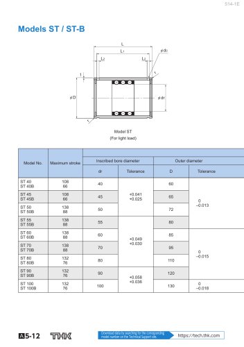 Models ST / ST-B
2 Pages
 Predicting the Rigidity
5 Pages
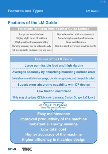 Features of the LM Guide
16 Pages
 PCT/PC
40 Pages
 Models SHS-C and SHS-LC
2 Pages
 Models SSR-XW and SSR-XWM
2 Pages
 Models SSR-XV and SSR-XVM
2 Pages
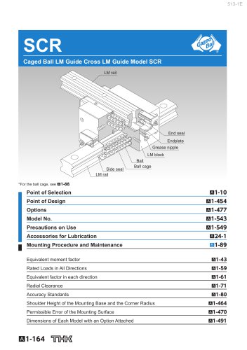 SCR
SCR8 Pages
 LM ACTUATOR GL
20 Pages
 HDR
HDR28 Pages
 RSX
RSX6 Pages
 Fix Stages
4 Pages
 Finite Stroke LM Guide EPF
12 Pages
 LM ACTUATOR GL-N
28 Pages
 LM Actuator TY
16 Pages
 Clean-Room Actuator Model CSKR
20 Pages


Archived catalogs
 Model SSR-XTB
2 Pages
 Catalogue Caged Ball LM Guide
23 Pages
 Low Price Actuator Model VLA
16 Pages
 Ball Spline Series
24 Pages
 Cross-Roller Ring Series
28 Pages
 High-temparature LM Guide Series
28 Pages
 Model HR Separate Type
20 Pages
 LM Actuator Model TY
16 Pages
 Guide Ball Bush LG
8 Pages
 Limited-stroke LM Guide
12 Pages
 LM Actuator Model GL-N
28 Pages
 RoD Actuato
12 Pages
 Product Ordering Guide
8 Pages
 LM Guide Actuator KR
68 Pages


