- Products
- Catalogs
- News & Trends
- Exhibitions
LM Actuator Model TY

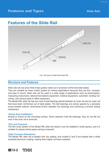
LM Actuator Model TY
- High-Speed and Long Stroke: Suitable for strokes up to 4749 mm with a belt drive method.
- Maintenance-Free Operation: Features a Caged Ball LM Guide and QZ Lubricator for reduced friction and extended maintenance intervals.
- Dustproof Option: A stainless steel cover is available to protect against foreign matter, though it limits maximum base length and speed.
- Lightweight Structure: Constructed with narrow-width aluminum extrusion for reduced weight.
- Motor Brackets: Available for both concentric and orthogonal axis type reducers, supporting various motor outputs and reduction ratios.
- Sensors: Compatible with photo and proximity sensors, mounted in the T-groove of the base.
- Mounting: Options for horizontal mounting with base fixing brackets and nuts.
Catalog excerpts
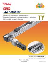
Optimal for high speed and long stroke Long term maintenance-free operation is actualized Lightweight, compact structure For details, visit THK at www.thk.com ^Product information is updated regularly on the THK website. TOKYO. JAPAN
Open the catalog to page 1
This belt drive actuator has a caged ball LM Guide combined with a lightweight and compact aluminum base. Options such as a stainless steel cover, a motor bracket or a sensor make it useful for a variety of applications. 11. Optimal for long stroke high speed conveyance A maximum stroke of 4749 mm* is possible due to the belt drive method. A maximum travel speed of 3400 mm/s is possible when an AC servomotor (rated rotational speed 3000 min.-1) . * Stroke between the mechanical stoppers Maximum Travel Speed Note 1) Please note that when the stroke is short, it may not reach the maximum travel...
Open the catalog to page 2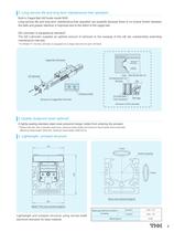
2. Long service life and long term maintenance-free operation Built-in Caged Ball LM Guide model SHS. Long service life and long term maintenance-free operation are possible because there is no mutual friction between the balls and grease retention is improved due to the effect of the caged ball. QZ Lubricator is equipped as standard*. The QZ Lubricator supplies an optimal amount of lubricant to the raceway of the LM rail, substantially extending maintenance intervals. * For Model TY, the QZ Lubricator is equipped on a single side only for each LM block. ator Case Application & spreading QZ lubricator...
Open the catalog to page 3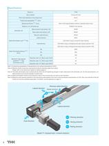
Note 1) Positioning repeatability is standardized at an ambient temperature of 20°C. Note 2) Effective stroke is less than mechanical stroke for stainless steel cover option. Please refer to the dimensions tables for details (page 6). Note 3) The static permissible load is determined by either the bolt tightening strength or static rated load of the LM Guide unit. For the axial direction, it is determined by the torsional strength of pulley shaft. Note 4) Static permissible moment is the maximum value of the moment that can load on each direction. Note 5) Maximum load capacity guideline is the...
Open the catalog to page 4
I Model Number Chart For concentric type reducer For orthogonal axis type reducer C: With a stainless steel cover
Open the catalog to page 5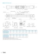
Grease nipple /(Same position on the opposite side) Base length Input shaft Detailed View of E Detailed View of F ' When installing an orthogonal axis type reducer, please note that the input shaft will differ (see page 8). Note 1) Above figure shows the slider in mid-stroke. Note 2) Please contact THK for strokes other than those listed above. Note 3) Please install the unit using the T-slot (E section) on the side (see page 12).
Open the catalog to page 6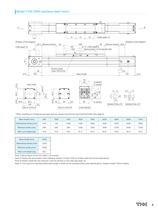
I Model TY20 (With stainless steel cover) /(Same position on the opposite side) Grease nipple Base length Input shaft Detailed View of E Detailed View of F ' When installing an orthogonal axis type reducer, please note that the input shaft will differ (see page 8). Note 1) Above figure shows the slider in mid-stroke. Note 2) Please use the actuator within effective strokes. Contact THK for strokes other than those listed above. Note 3) Please install the unit using the T-slot (E section) on the side (see page 12). Note 4) The maximum manufacturable base length is 3540 mm for stainless steel cover...
Open the catalog to page 7
Motor brackets for various reducers are available. Table of Supported Motor Bracket for Concentric Type Reducer Table of Supported Motor Bracket for Orthogonal Axis Type Reducer Note 1) The load inertial moment is bigger because this product uses the belt drive method. Using a reducer is recommended. Note 2) Please see Shimpo Drives, Inc.'s catalog for detailed reducer specifications. Note 3) The orthogonal axis type reducer is a special specification. Please contact THK for details. Note 4) If a reducer is installed by THK, please provide the motor manufacturer and model number of the motor.
Open the catalog to page 8
I Motor bracket dimensions Motor bracket for concentric type reducer Dimensions of Motor Bracket for Concentric Type Reducer unit: Motor bracket for orthogonal axis type reducer Dimensions of Motor Bracket for Orthogonal Axis Type Reducer unit: Note) Keys are not included in the reducer. Please have keys ready when installing the reducer.
Open the catalog to page 9
Concentric type reducer Orthogonal axis type reducer Dimensions When Mounting the Reducer
Open the catalog to page 10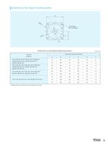
I Dimensions of the reducer mounting section Dimensions of the Reducer Mounting Section unit: * Please select the dimensions according to the motor.
Open the catalog to page 11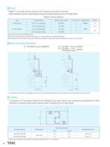
Model TY can equip various sensors to the T-groove at the side of the base. When selecting a sensor, please specify using the corresponding code from the table below. Tables of Various Sensors Note 1) All sensor ouputs are NPN outputs. Note 2) N.O. contact point is a normally-open type; N.C. contact point is a normally-closed type. Note 3) Sensors are mounted on the product before being shipped. Please note that a photosensor connector is not included. I Sensor mounting dimensions * The direction of the sensor is changeable. The sensor can be removed by sliding the sensor mounting nut from the...
Open the catalog to page 12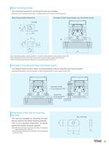
Base mounting bracket The mounting brackets for mounting the base are available. Note) this is not a standard attachment, so please specify the number of pieces required. 9 Base fixing bracket dimensions Example of base fixing bracket use (horizontal mount) 8.5 13 R7.5 12 M8 18.2 8.5 22.5 15 12 8 19.5 13 15 26 8 19.5 27 9 27 8.5 15 26 15 13 26 15 9 through 27 18.2 22.5 15 8 19.5 100 12 M8 Note 1) Mounting position must be horizontal. If a wall mounting position is used, please contact THK. Note 2) Mounting intervals of the base fixing brackets should be approximately 250 to 300 mm. 18.2 * Mount...
Open the catalog to page 13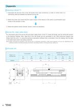
© Calculate the service life of the LM Guide from load conditions in order to check that It Is sufficiently safe and satisfies the desired service life. © Select the motor and check that the output torque of the reducer Is the same as permissible Input torque of the actuator or less. CÍ) Select the options (motor bracket, sensor, cover) as necessary. I Service life / static safety factor For Information about the service life and static safety factor of the TY model LM Guide, see the LM Guide section in the General Catalog. Also, rated life of the LM Guide can be calculated In the THK's technical...
Open the catalog to page 14All THK catalogs and technical brochures
 Models ST / ST-B
2 Pages
 Predicting the Rigidity
5 Pages
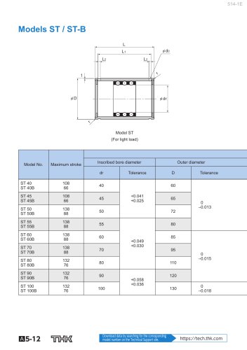
 Features of the LM Guide
16 Pages
 PCT/PC
40 Pages
 Models SHS-C and SHS-LC
2 Pages
 Models SSR-XW and SSR-XWM
2 Pages
 Models SSR-XV and SSR-XVM
2 Pages
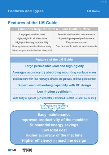
 SCR
SCR8 Pages
 LM ACTUATOR GL
20 Pages
 HDR
HDR28 Pages
 RSX
RSX6 Pages
 Fix Stages
4 Pages
 Finite Stroke LM Guide EPF
12 Pages
 LM ACTUATOR GL-N
28 Pages
 LM Actuator TY
16 Pages
 Clean-Room Actuator Model CSKR
20 Pages


Archived catalogs
 Model SSR-XTB
2 Pages
 Catalogue Caged Ball LM Guide
23 Pages
 Low Price Actuator Model VLA
16 Pages
 LM Guide Actuator Model KR
92 Pages
 Ball Spline Series
24 Pages
 Cross-Roller Ring Series
28 Pages
 High-temparature LM Guide Series
28 Pages
 Model HR Separate Type
20 Pages
 Guide Ball Bush LG
8 Pages
 Limited-stroke LM Guide
12 Pages
 LM Actuator Model GL-N
28 Pages
 RoD Actuato
12 Pages
 Product Ordering Guide
8 Pages
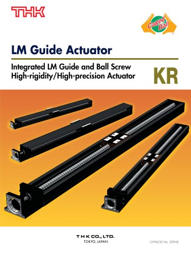 LM Guide Actuator KR
68 Pages


- Metal nut
- THK linear guide
- Metal stand
- Plain bearing
- Bearing unit
- Metal plain bearing
- Telescopic slide
- Slewing bearing
- Steel linear guide
- THK ball bearing linear guide
- Rod end
- Metal bushing
- Ball screw
- Slide carriage block
- Cantilever axis
- THK compact linear guide
- Single-row slewing ring
- THK precision linear guide
- Roller slide