- Products
- Catalogs
- News & Trends
- Exhibitions
Limited-stroke LM Guide
1 /12Pages

Limited-stroke LM Guide
1 /12Pages
Catalog excerpts
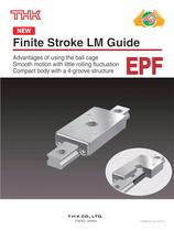
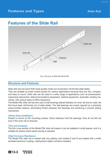
Finite Stroke LM Guide Advantages of using the ball cage Smooth motion with little rolling fluctuation Compact body with a 4-groove structure TOKYO. JAPAN
Open the catalog to page 1
Ball Cage Effect The early forms of ball bearings were full-ball types without ball cages. Friction between balls caused loud noise, made high-speed rotation impossible, and shortened the service life. Twenty years later, a Caged Ball design was developed for ball bearings. The new design enabled high-speed rotation at a low noise level and extended the service life, despite the reduced number of balls used. It marked a major development in the history of ball bearings. Similarly, the quality of needle bearings was significantly improved by the caged needle structure. With cage-less, full-ball...
Open the catalog to page 2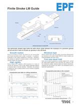
Finite Stroke LM Guide Cross section (DB structure) Internal structure of model EPF The spherically shaped cage holds the balls which rotate between the raceways of a precision ground LM rail and the 4 rows of circular arc grooves in the LM block. # Smooth motion Since its stroke is finite, the balls do not recirculate and travel smoothly even under a preload. In addition, fluctuation of the rolling resistance is minimum. Therefore, the product is optimal in places where a short stroke and smooth motion are required. # High rigidity Since model EPF adopts a DB structure in 4 rows of circular...
Open the catalog to page 3
# Utilization of the Ball Cage Since the cage is resin-molded, metal to metal contact between balls is eliminated, and acceptable running noise, low particle generation and long service life are achieved. # Utilization of the Ball Cage Since the cage is resin-molded into a spherical shape, the lubricant is retained in a grease pocket and long-term maintenance-free operation is achieved. Model EPF - Product Overview Major Applications | semiconductor manufacturing machines / medical equipment /
Open the catalog to page 4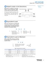
Model EPF - Product Overview Rated Loads in All Directions Model EPF is capable of receiving loads in all four directions: radial, reverse-radial and lateral directions. The basic load ratings are equal in the four directions (radial, reverse-radial and lateral directions). Their actual values are Reverse-radial direction Radial direction When the LM block of model EPF receives loads in the radial, reverse-radial and lateral directions simultaneously, the equivalent load is obtained in the equation below. : Equivalent load (N) PR : Radial load (N) • Radial direction PL : Reverse-radial load (N)...
Open the catalog to page 5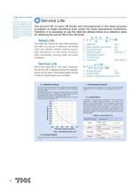
*1 : Basic dynamic load rating The basic dynamic load rating (C) indicates the load with constant direction and magnitude, under which the rated life (L) is 50 km when Guide units independently operating under the same The service life of each LM Guide unit manufactured in the same process is subject to slight variations even under the same operational conditions. Therefore, it is necessary to use the rated life defined below as a reference value for obtaining the service life of the LM Guide. • Rated Life The rated life means the total travel distance that 90% of a group of identical LM Guide...
Open the catalog to page 6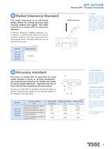
Model EPF - Product Overview Radial Clearance Standard The radial clearance of an LM Guide greatly affects its running accuracy, load carrying capacity and rigidity. The radial clearance of model EPF is optimally In general, selecting a negative clearance, (i.e., a preload*1 is applied) while taking into account possible vibrations and impact generated from reciprocating motion, favorably affects the service Radial clearance load applied to the rolling block in advance in order adjusted before shipment Accuracy standard Accuracy of model EPF is specified for each model number in terms of running...
Open the catalog to page 7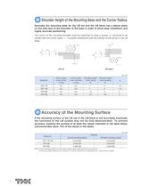
Shoulder Height of the Mounting Base and the Corner Radius Normally, the mounting base for the LM rail and the LM block has a datum plane on the side face of the shoulder of the base in order to allow easy installation and highly accurate positioning. The corner of the mounting shoulder must be machined to have a recess, or machined to be smaller than the corner radius "r," to prevent interference with the chamfer of the LM rail or the LM (3 Accuracy of the Mounting Surface If the mounting surface of the LM rail or the LM block is not accurately machined, the functions of the LM system may not...
Open the catalog to page 8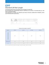
Standard LM Rail Length The following table shows the standard LM rail lengths of model EPF. We recommend the corresponding values for dimension G, as shown in the table below, for rails with non-standard lengths. If the dimension G is longer, the respective part tends to become unstable after installation, which may adversely affect the accuracy. Standard LM rail lengths of model EPF Note: LM rail lengths other than the standard LM rail lengths (Lo) may also be available. Contact THK for details.
Open the catalog to page 9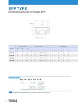
Dimensional Table for Model EPF Rail material: stainless steel Accuracy symbol *:The material of the LM rail is stainless steel as standard. This model number indicates that an LM rail and an LM block constitute one set.
Open the catalog to page 10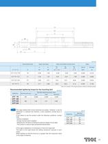
Note: AFJ Grease (THK original grease) is filled as standard grease. Recommended tightening torque for the mounting bolt The cage holding balls moves extremely accurately. However, it may be displaced if it receives the machine' s drive vibrations, inertial force or If you desire to use the product under the following conditions, contact •Vertical installation •A large moment load is applied • Stopping the LM block by letting the external stopper hit the table •The product is used at high acceleration/deceleration If the cage is displaced, it is necessary to force the cage back. The table on...
Open the catalog to page 11
TfiHlK Finite Stroke LM Guide Model EPF • Disassembling components may cause dust to enter the system or degrade the mounting accuracy of parts. Do not disassemble • Tilting the LM block or LM rail may cause them to fall by their own weights. • Dropping or hitting the LM Guide may damage it. Applying an impact to the LM Guide could also cause damage to its function even if the guide looks intact. • Thoroughly remove anti-corrosion oil and feed a lubricant before using the product. • Do not mix lubricants of different physical properties. • In locations exposed to constant vibrations or in special...
Open the catalog to page 12All THK catalogs and technical brochures
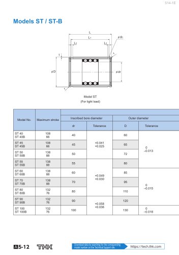 Models ST / ST-B
2 Pages
 Predicting the Rigidity
5 Pages
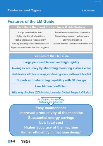 Features of the LM Guide
16 Pages
 PCT/PC
40 Pages
 Models SHS-C and SHS-LC
2 Pages
 Models SSR-XW and SSR-XWM
2 Pages
 Models SSR-XV and SSR-XVM
2 Pages
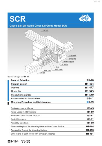 SCR
SCR8 Pages
 LM ACTUATOR GL
20 Pages
 HDR
HDR28 Pages
 RSX
RSX6 Pages
 Fix Stages
4 Pages
 Finite Stroke LM Guide EPF
12 Pages
 LM ACTUATOR GL-N
28 Pages
 LM Actuator TY
16 Pages
 Clean-Room Actuator Model CSKR
20 Pages


Archived catalogs
 Model SSR-XTB
2 Pages
 Catalogue Caged Ball LM Guide
23 Pages
 Low Price Actuator Model VLA
16 Pages
 LM Guide Actuator Model KR
92 Pages
 Ball Spline Series
24 Pages
 Cross-Roller Ring Series
28 Pages
 High-temparature LM Guide Series
28 Pages
 Model HR Separate Type
20 Pages
 LM Actuator Model TY
16 Pages
 Guide Ball Bush LG
8 Pages
 LM Actuator Model GL-N
28 Pages
 RoD Actuato
12 Pages
 Product Ordering Guide
8 Pages
 LM Guide Actuator KR
68 Pages


- Nut
- Metal nut
- THK linear guide
- Metal stand
- Plain bearing
- Bearing unit
- Metal plain bearing
- Telescopic slide
- Slewing bearing
- Steel linear guide
- THK ball bearing linear guide
- Rod end
- Metal bushing
- Ball screw
- Slide carriage block
- Cantilever axis
- THK compact linear guide
- Single-row slewing ring
- THK precision linear guide
- Roller slide