 Website:
Thames Side Sensors
Group: Tecnicas
Catalog excerpts

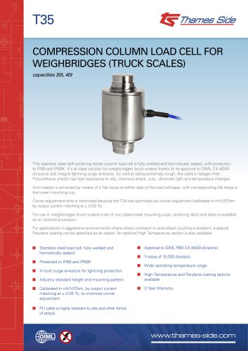
T35 COMPRESSION COLUMN LOAD CELL FOR WEIGHBRIDGES (TRUCK SCALES) capacities 30t, 40t This stainless steel self-centering rocker column load cell is fully welded and hermetically sealed, with protection to IP68 and IP69K. It’s an ideal solution for weighbridges (truck scales) thanks to its approval to OIML C4 (4000 divisions) and integral lightning surge arrestors. As well as being extremely tough, the cable’s halogen-free Polyurethane sheath has high resistance to rats, chemical attack, cuts, ultraviolet light and temperature changes. Anti-rotation is achieved by means of 2 flat faces on either side of the load cell base, with corresponding flat faces in the lower mounting cup. Corner adjustment time is minimised because the T34 has optimized pre-corner adjustment (calibrated in mV/V/Ohm by output current matching at ± 0.05 %). For use in weighbridges (truck scales) a set of zinc plated steel mounting cups, centering discs and bolts is available as an optional accessory. For applications in aggressive environments where stress corrosion or acid attack could be a problem, a special Parylene coating can be specified as an option. An optional High Temperature version is also available. ■ Stainless steel load cell, fully welded and hermetically sealed ■ Protected to IP68 and IP69K ■ In-built surge arrestors for lightning protection ■ Industry standard height and mounting pattern ■ Calibrated in mV/V/Ohm, by output current matching at ± 0.05 %, to minimise corner adjustment ■ Approval to OIML R60 C4 (4000 divisions) ■ Y-value of 15,000 divisions ■ Wide operating temperature range ■ High Temperature and Parylene coating options available ■ 3 Year Warranty ■ PU cable is highly resistant to rats and other forms of at
Open the catalog to page 1
technical specification... Mandatory direction of tilt and truck motion Important: Bumper stops must be fitted to the weighbridge / truck scale and adjusted to limit movement to a recommended min. 3mm, max. 7mm in both the longitudinal and transverse directions. This is essential in order to avoid damage to the equipment. Refer to the critical dimensions f and G below (**). Supplied Load Cell Capacity (E max) Load cell specification Accuracy Class Combined error G max. permitted lateral movement ** Minimum load cell verification interval (vmin) = E max / Y Temperature Effect on Zero Balance...
Open the catalog to page 2All Thames Side Sensors catalogs and technical brochures
-
VC3500 Load cell Data sheet
4 Pages
-
T85-T Load cell Data sheet
2 Pages
-
T85-N Load cell Data sheet
2 Pages
-
T85 Load cell Data sheet
4 Pages
-
T95 Load cell Data sheet
2 Pages
-
T68 Load cell Data sheet
2 Pages
-
T66 Load cell Data sheet
2 Pages
-
T65 Load cell Data sheet
2 Pages
-
T64 Load cell Data sheet
2 Pages
-
T61 Load cell Data sheet
2 Pages
-
T60 Load cell Data sheet
2 Pages
-
T38 Load cell Data sheet
2 Pages
-
T35D load cell data sheet
2 Pages
-
T34D Load cell Data sheet
2 Pages
-
T30 Load cell Data sheet
2 Pages
-
T20 Load cell Data sheet
2 Pages
-
T16 Load cell Data sheet
2 Pages
-
T12A Load cell Data sheet
2 Pages
-
T12 Load cell Data sheet
2 Pages
-
T6 Load cell Data sheet
2 Pages
-
T5 Load cell Data sheet
2 Pages
-
T4 Load cell Data sheet
2 Pages
-
T2 Load Cell Datasheet
2 Pages
-
650 Load Cell Data Sheet
2 Pages
-
T11 Load Cell
2 Pages
-
LA66 Weighing Assembly
2 Pages


