- Catalogs
- TERMYA MEDIDA Y CONTROL
- PMA-UNIFLEX-CI45
PMA-UNIFLEX-CI45
1 /8Pages

PMA-UNIFLEX-CI45
1 /8Pages
Catalog excerpts

UNIFLEX CI 45 Universal transmitter Compact design Display & operating functions Communication features High resolution Fast cycle times Two universal inputs & universal output Two relay outputs Counter/frequency input, frequency output Customer-specific linearization Measurement value correction Min/max indicator ('slave pointer') ^ Compact design, only 22,5 mm wide > Clips onto top-hat DIN rail ^ Plug-in screw terminals or spring-clamp connectors ^ Dual-line LC display with additional display elements ^ Process values always in view ^ Convenient 3-key operation ^ Direct communication between mounted transmitters, fieldbus connections via bus coupler ^ Up to two universal inputs with high signal resolution (>15 bits) ^ Universal output with high resolution (14 bits) as combined voltage/current output > One or two relay outputs ^ combined counter or frequency input, frequency output > Quick response; only 100 ms cycle time, i.e. also suitable for fast signals ^ Customer-specific linearization ^ Measurement value correction (offset or 2-point) ^ Min/max indicator ('slave pointer') ^ Logical linking of digital outputs, e.g. for common alarms > Preset for output value ^ Measurement, scaling, and separation of electrical signals, e.g. for: ^ Heat treatment plants ^ Drying equipment ^ Furnace builders ^ Metallurgy ^ Kilns ^ General machine building ^ Research and development ^ Speed control, flow measuring, event counting, energy consumption collecting ^ etc. UNIFLEX CI 45 transmitters are designed to give precise and cost-effective signal detection and processing tasks. Every CI 45 has at least one universal input, one universal output and a relay. Optionally, the transmitter can be fitted with an additional relay, with a second universal input and counter or frequency input. Optionally, the voltage output can also be used as frequency output. Galvanic isolation is provided between inputs and outputs as well as from the supply voltage and the communication interfaces. Mounting The compact CI 45 is clipped onto a top-hat DIN rail, and can also be unmounted very simply. All connections are of the plug-in type, so that a transmitter can be replaced very quickly without disturbing the wiring. Display and operation The two-line LC display permits simultaneous indication of the measured value and all of the unit's operating functions. Moreover, a LED and 4 other display elements give a reliable indication of operating status, operating mode, and error messages. The user-configurable engineering unit of the measured value can be included in the display. By means of the extended Operating Level, it is possible to show any signal or parameter in the 2nd display line. Interfaces and Engineering Tools The transmitter settings are also configurable by means of an Engineering Tool. Via the BlueControl® software, including the transmitter simulation and especially the convenient connection via the BluePort® front interface, the
Open the catalog to page 1
Table 1: Thermocouple input * For INP1: high-impedance, without break monitoring for INP2: high impedance, break monitoring always active Thermocouples (Table 1) Input resistance: > 1 MQ Input circuit monitor: sensor break, polarity Cold-junction compensation • Internal - additional error: typical <+ 0.5 K Break monitoring Sensor current: < 1 pA Operating sense configurable Resistance thermometer (Table 2) if using INP2) Lead resistance: max. 30 Q (max. at range end) Input circuit monitoring: break and short circuit Measurement span Separated into ranges Physical measurement...
Open the catalog to page 2
14 bits Output follows the input: < 540 ms < 2% <±1 % 0...130 kHz The BlueControl® software enables the internal characteristic curve for the KTY 11-6 temperature sensor to be adapted. Current and voltage measurement (Table 3) Span start and span: anywhere within the measurement range Scaling: freely selectable —1999...9999 Input circuit monitoring (current): 12,5% below span start (2 mA) O2- measuring (option) EMI-measuring by means of INP1 (high-impedance mV-inputs) suitable for probes with - constant sensor temperature (heated probes), setting by means of parameter - measured...
Open the catalog to page 3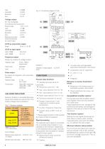
Load effect: < 0,02% Voltage output 0/2...10V, configurable not continuous short-circuit proof Dynamic range: Load: Load effect: Resolution: Error: Additional error when using simultaneously the current output OUT3 as logic signal Load < 700 [ 0/< 23 mA Frequency output Output by means of voltage output frequency range: 0, 0.25...1000 Hz (square wave) Output value: adjustable Isolation: between in-/output against < 33 V AC earth: Pulse output by means of integrator with automatic resetting frequency range: 0...5 Hz max. 5 Imp/s Puls duration: 100ms (INP1 measuring) GALVANIC...
Open the catalog to page 4
The engineering unit for the measured value can either be selected from a predefined list of standard units, or it can be defined by the user (BlueControl®). The unit appears in the second line of the display. Display of engineering units The transmitter contains a 1st-order mathematical filter with adjustable time constant and bandwidth. The bandwidth is the adjustable tolerance range within which the filter is active above and below the process value. Measurement value changes in excess of the adjusted bandwidth are not filtered. MAINTENANCE MANAGER LIMIT VALUE FUNCTIONS Max, Min or Max/Min...
Open the catalog to page 5
POWER SUPPLY Depending on ordered version: AC supply Voltage: 90...260VAC Supply only from safety electrical low voltage (SELV). * Devices with system option: They are supplied via the bus connector from bus coupler or power supply module. Behaviour with power failure Configuration and parameter settings: Permanent storage in EEPROM BLUEPORT® FRONT INTERFACE Connection to the transmitter front via a PC adapter (see 'Accessories'). The BlueControl® software enables the CI 45 to be configured, parameters set, and operated. RS485 Connection via bus connector fitted in the top-hat rail. Screened...
Open the catalog to page 6All TERMYA MEDIDA Y CONTROL catalogs and technical brochures
 PMA-UNIFLEX-SG45
8 Pages
 PMA-UNIFLEX-CI35
6 Pages
 PARTLOW-DataVU-7
21 Pages
 PARTLOW-MRC-5000
4 Pages
 PARTLOW-MRC-7000
6 Pages
 PARTLOW-MRC-8000
4 Pages
 PARTLOW-MRC-9000
4 Pages
 serv-rite wire
40 Pages
 SENSORES CAPACITIVOS
7 Pages
 HUMEDAD
2 Pages

- Kiln
- Electrical cable
- Data connector
- Chamber kiln
- Electric furnace
- Metal connector
- Copper cable
- Copper electrical cable
- Resistance temperature sensor
- Pressure transmitter
- Polymer connector
- Calibration system
- Analog pressure transmitter
- Digital temperature control
- Cable sleeve
- Multi-strand cable
- Multi-wire electrical cable
- Digital indicator