- Catalogs
- TERMYA MEDIDA Y CONTROL
- PMA-UNIFLEX-CI35
PMA-UNIFLEX-CI35
1 /6Pages

PMA-UNIFLEX-CI35
1 /6Pages
Catalog excerpts
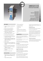
UNIFLEX CI 35Universal transmitter rail line Compact design Display & operating functions High resolution Fast cycle times universal input/universal output relay output Customer-specific linearization Measurement value correction Min/max indicator ('slave pointer') ^ Compact design, only 22,5 mm wide ^ Clips onto top-hat DIN rail ^ Plug-in screw terminals or spring-clamp connectors > Dual-l ine LC display with additional display elements ^ Process values always in view ^ Convenient 3-key operation ^ Universal input with high signal resolution (>15 bits) ^ Universal output with high resolution (14 bits) as combined voltage/current output ^ Relay output ^ Quick response; only 100 ms cycle time, i.e. also suitable for fast signals ^ Customer-specific linearization ^ Measurement value correction (offset or 2-point) ^ Min/max indicator ('slave pointer') ^ Preset for output value ^ Measurement, scaling, and separation of electrical signals, e.g. for: ^ Heat treatment plants ^ Drying equipment ^ Furnace builders ^ Metallurgy ^ Kilns ^ General machine building ^ Research and development ^ etc. DESCRIPTION UNIFLEX CI 35 transmitters are designed to give precise and cost-effective signal detection and processing tasks. Every CI 35 has one universal input, one universal output and a relay. Galvanic isolation is provided between inputs and outputs as well as from the supply voltage. Mounting The compact CI 35 is clipped onto a top-hat DIN rail, and can also be unmounted very simply. All connections are of the plug-in type, so that a transmitter can be replaced very quickly without disturbing the wiring. Display and operation The two-line LC display permits simultaneous indication of the measured value and all of the unit's operating functions. Moreover, a LED and 4 other display elements give a reliable indication of operating status, operating mode, and error messages. The user-configurable engineering unit of the measured value can be included in the display. By means of the extended Operating Level, it is possible to show any signal or parameter in the 2nd display line. Engineering Tools The transmitter settings are also configurable by means of an Engineering Tool. Via the BlueControl® software, including the transmitter simulation and especially the convenient connection via the BluePort® front interface, the user can solve the task in hand without having to work through operating instructions. Of course, practically all settings can also be made from the device front. Password protection If required, unauthorized access to the various Operating Levels can be prevented with a password, or an entire level can be blocked.
Open the catalog to page 1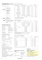
UNIVERSAL INPUT INP1 Type: single ended, exept thermocouples Resolution: Decimal point: Digital input filter: Scanning cycle: Linearization: Measurement value correction: Limiting frequency: > 15 bits 0 to 3 decimals adjustable 0.0...999.9 s 100 ms (only INP1) 31 segments, adaptable with BlueControl® 2-point or offset 1.7 Hz Thermocouples (Table 1) Input resistance: > 1 MQ Input circuit monitor: sensor break, polarity Cold-junction compensation • Internal - additional error: typical <+ 0.5 K Break monitoring Sensor current: < 1 pA Operating sense configurable Resistance thermometer...
Open the catalog to page 2
14 bits Output follows the input: < 540 ms < 2% <_1 % 0...130 kHz safety isolation functional isolation RELAY OUTPUT OUT1 Type: 2 NO contact max. 2 Aat48...62 Hz, resistive load Min. contact rating: 6V, 1 mA DC cycles (at 250V AC, resistive load) (electrical): Note: If the relay OUT1 Is used to operate external contactors, these must be fitted with RC snubber circuits to manufacturer specIfIcatIons to prevent excessIve voltage peaks at switch-off. OUT3AS UNIVERSAL OUTPUT Parallel current/voltage output with common 'minus' terminal (combined use only in galvanically isolated circuits)....
Open the catalog to page 3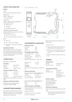
DISPLAY AND OPERATION Display LCD: dual-line plus additional display elements Upper line: 4 digits, 7-segment LCD • for process value Lower line: 5 digits, 14-segment LCD; configurable contents (via BlueControl®) • Engineering unit • Parameters • Extended Operating Level Additional display elements 2 display elements (bars in the lower line of the LCD, identified as 1, 2, F, E) • Bars 1 and 2: OUT1 active • Bar E: Entry has been made in the error list LED: • Green = OK • Red = limit value Lim1 triggered • Red blinking = internal fault, configuration mismatch Operating functions Only three keys...
Open the catalog to page 4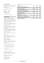
Mounting method Clip-on rail mounting (35 mm top-hat rail to EN 50 022). Locked by means of metal catch in housing base. Close-packed mounting possible. Mounting position: vertical Weight: 0.18 kg CERTIFICATION • CE certified • UL/cUL certified (applied for) Table 4: BlueControl®, versions und functions: Functionality Mini Basic Expert parameter and configuration setting yes yes yes download: writes an engineering to the device online-mode / visualisation SIM only yes creation of user defined linearizations yes yes yes configuration of extended operation level upload: reads an engineering...
Open the catalog to page 5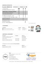
ORDERING INFORMATION 00 1 universal-input with display and BluePort®-interface UL/cUL-certified (applied for) U Q Connector set with screw terminals 4 pieces 9407-998-07101 2 Connector set with spring-clamp terminals 4 pieces 9407-998-07111 ADDITIONAL ACCESSORIES_ PC adapter for the BluePort* front interface USB serial adaptor (USB to RS 232)_ BlueControT Mini German/English BlueControl with Basic license rail line German/English BlueControl* with Expert license rail line German/English > Please also order the associated documentation: Description Operating...
Open the catalog to page 6All TERMYA MEDIDA Y CONTROL catalogs and technical brochures
 PMA-UNIFLEX-SG45
8 Pages
 PMA-UNIFLEX-CI45
8 Pages
 PARTLOW-DataVU-7
21 Pages
 PARTLOW-MRC-5000
4 Pages
 PARTLOW-MRC-7000
6 Pages
 PARTLOW-MRC-8000
4 Pages
 PARTLOW-MRC-9000
4 Pages
 serv-rite wire
40 Pages
 SENSORES CAPACITIVOS
7 Pages
 HUMEDAD
2 Pages

- Kiln
- Electrical cable
- Data connector
- Temperature probe
- Chamber kiln
- Electric furnace
- Metal connector
- Copper cable
- Copper electrical cable
- Resistance temperature sensor
- Pressure transmitter
- Polymer connector
- Calibration system
- Analog pressure transmitter
- Digital temperature control
- Cable sleeve
- Multi-strand cable
- Multi-wire electrical cable
- Digital indicator