- Catalogs
- TERMYA MEDIDA Y CONTROL
- PARTLOW-DataVU-7
PARTLOW-DataVU-7
1 /21Pages

PARTLOW-DataVU-7
1 /21Pages
Catalog excerpts
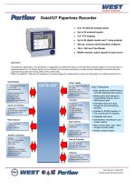
DataVU7 Paperless Recorder 6 to 18 internal analog inputs Up to 24 external inputs 5.5’’ TFT Display Up to 24 digital inputs and 7 relay outputs Set-up, Comms and Evaluation software 144 x 144 mm Front Bezel Maths module, batch reports & web server The DataVU7 represents a new generation of paperless recorders that stand out through their modular design for the acquisition of measured data (3 to 18 internal inputs can be utilized), the innovative operating concept and high standards of security prevents unauthorized access and manipulation of the stored data. Within the DataVU7, data can be visualized in process images as measurement curves, as a bar graph or in alphanumerical form. Input/Outputs 0…18 analog inputs max. 0…24 binary inputs/outputs max. (max of 3 module slots, can be fitted with 6 analog inputs or 3 analog inputs & 8 binary inputs/outputs) Inputs via interface additionally up to 24 analog inputs and up to 24 binary inputs Power supply AC 100...240V +10/-15%, 48...63Hz AC/DC 20...30V, 48...63Hz (ELV) or 3 analog inputs and 8 binary inputs/outputs) Interface as standard 1x Ethernet 10/100 Mbits/sec 4x USB interfaces 1x RS232/RS485 1x RS232 (barcode reader) option: 1x PROFIBUS-DP Key Features Easy operation by control knob or touchpad (stainless steel version) Measurement data storage on CompactFlash memory card or USB memory stick Automatic read-out of data through the Communications Software Interface to SCADA systems, to PLC controls and PC systems Integrated web server Data memory Simultaneous recording for up to 3 batch reports internal memory 256 Mbytes Batch control (start, stop, texts) through barcode reader external memory CompactFlash card and USB memory stick Modbus master function Relay Outputs 1 relay (standard) additionally 6 relays (option) Display / Operation Display 5.5" TFT color display, 320 x 240 pixels, 256 colors Operation rotary knob or touchpad analog inputs or 3 analog inputs and 8 binary inputs/outputs) Internal Channels 18x math channels 18x logic channels 27x counters /integrators Software Setup program Evaluation software Communications software
Open the catalog to page 1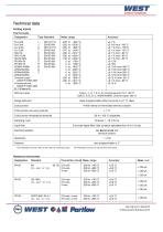
Analog inputs Thermocouple Type Standard Meas. range Control Solutions Fe-CuNi L Fe-CuNi J Cu-CuNi U Cu-CuNi T NiCr-Ni K NiCr-CuNi E NiCrSi-NiSi N Minimum span Type L, J, U, T, K, E, N, chromel-alumel, PL II: 100 °C Type S, R, B, D, C, W3Re/W26Re, chromel-copel: 500 °C Range start/end freely programmable within the limits, in 0.1 °C steps Cold junction Pt100 internal or thermostat external constant Cold junction accuracy (internal) Cold junction temperature (external) Sampling cycle Input filter 2nd order digital filter; filter constant adjustable from 0 to 10.0 sec Electrical...
Open the catalog to page 2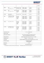
Control Solutions 1 The linearization accuracy refers to the maximum measuring range. The linearization accuracy is reduced with short spans.
Open the catalog to page 3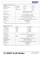
Control Solutions Resistance transmitter and potentiometer 1 The linearization accuracy refers to the maximum measuring range. The linearization accuracy is reduced with short spans. Input for DC voltage, DC current Basic range Shortest span Range start/end freely programmable within the limits in 0.01 mV steps burden voltage < 3 V burden voltage < 3 V Shortest span Range start/end Sampling cycle Input filter Electrical isolation freely programmable within the limits in 0.01 mA steps 2nd order digital filter; filter constant adjustable from 0 to 10.0 sec see Electrical dat and electrical isolation...
Open the catalog to page 4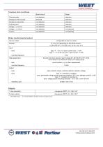
Control Solutions Transducer short circuit/break 1 With resistive load. 2 It is not permissible to mix SELV circuits and supply circuits. Ref DS-VU7-1 -EN-0212 © West Control Solutions 2012
Open the catalog to page 5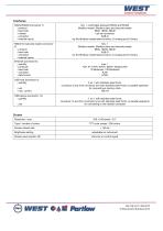
Control Solutions Ref DS-VU7-1 -EN-0212 © West Control Solutions 2012
Open the catalog to page 6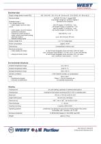
Control Solutions Electrical data Ref DS-VU7-1 -EN-0212 © West Control Solutions 2012
Open the catalog to page 7
Control Solutions 0 WEST €■*« Parihw Ref DS-VU7-1 -EN-0212 © West Control Solutions 2012
Open the catalog to page 8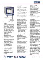
Control Solutions CompactFlash memory card and USB interfaces behind housing door. Control knob to rotate and press Instrument Description Hardware The DataVU7 recorder has a modular design. The basic form consists of a PSU board (incl. relays) and a CPU board (incl. Ethernet, RS232/RS485, RS232 for barcode reader and USB) Module slots 1, 2 and 3 can be fitted with the following options, 6 analog inputs, 3 analog inputs & 8 binary inputs/outputs or slot 3 can be fitted with a module with 6 relays. As an option, the PSU board can be equipped with PROFIBUS-DP communications. Data recording Measurements...
Open the catalog to page 9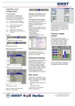
Control Solutions On the recorder The instrument is configured from the control knob (or with stainless steel front, from the touchpad) on the front panel under menu guidance. Shift current menu position (cursor) to the left or upwards. Shift current menu position (cursor) to the right or downwards. When the control knob is pressed, the current function is executed. Integrated user lists (different users with different authorizations) protect the recorder against unauthorized access. Through the setup program As an alternative to the configuration from the control knob on the recorder, the instrument...
Open the catalog to page 10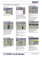
Visualization on the instrument Bar graph presentation Operator level Vertical diagram Recorder chart presentation of analog and binary channels Display of scaling and limit markers of a channel (can be switched on/off) Numerical display of current analog channels Bar graph presentation of analog channels On / Off presentation of binary channels Display of current analog channels with scaling and limit markers Color change of bar graph to red when limits are infringed Process image Numerical presentation Large numerical presentation of analog channels, including the channel name and description...
Open the catalog to page 11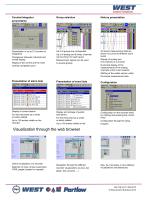
Counter/integrator presentation Group selection History presentation Presentation of up to 27 counters or integrators All stored measurement data are shown as curves at different zoom levels Changeover between individual and overall display Display of the current and the most recently completed count Up to 6 analog and 6 binary channels can be shown for each group Measurement signals can be used in several groups Display of scaling and limit markers of a channel Numerical display of the measurements of the analog channels at the cursor position Shifting of the visible section within the stored...
Open the catalog to page 12All TERMYA MEDIDA Y CONTROL catalogs and technical brochures
 PMA-UNIFLEX-SG45
8 Pages
 PMA-UNIFLEX-CI45
8 Pages
 PMA-UNIFLEX-CI35
6 Pages
 PARTLOW-MRC-5000
4 Pages
 PARTLOW-MRC-7000
6 Pages
 PARTLOW-MRC-8000
4 Pages
 PARTLOW-MRC-9000
4 Pages
 serv-rite wire
40 Pages
 SENSORES CAPACITIVOS
7 Pages
 HUMEDAD
2 Pages

- Connector
- Kiln
- Electrical cable
- Data connector
- Temperature probe
- Chamber kiln
- Electric furnace
- Metal connector
- Copper cable
- Copper electrical cable
- Resistance temperature sensor
- Pressure transmitter
- Polymer connector
- Calibration system
- Analog pressure transmitter
- Digital temperature control
- Cable sleeve
- Multi-strand cable
- Multi-wire electrical cable
- Digital indicator