HUMEDAD
1 /2Pages

HUMEDAD
1 /2Pages
Catalog excerpts
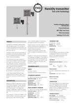
Humidity transmitterTwo-wire technology Humidity and humidity combined with temperature Freely selectable span MIN- / MAX- value memory Wall or duct mounting Conformity ± 1% rH /± 0,4% TECHNICAL DATA Humidity is presented in various methods, as relative value in % rH, (ratio of moisture distributed in the air to the maximum of moisture in air), or absolute as g H2O/Nm3dry air1*. Humidity transmitters are especially designed for monitoring of relative humidity in air conditioning systems as also within industrial processes. The used two-wire technology features easy installation because supply and signal are united and running via the same pair of wires. Combined humidity and temperature measurement with a second sensing element (-Pt1000-) provide not only for storage and air conditioning special features by simplified mounting and wiring. Local digital display features easy reading as also scaling of span. An internal lock prevents unauthorized access. Relative humidity is detected by means of a Polymer capacitor, whose capacity changes with effect to the moisture in the surrounding air. The capacitive change is calibrated in relative humidity and trans- formed into the 4...20 mA signal. This capacitor is, like the Pt1000 in the combi-version, mounted inside a supporting tube with protective cage, which protects against mechanical damage and external impurities. Digital operation permits adaption onto sensor characteristics (separate for temperature and moisture and is located inside the housing. Electrical connection is performed with an angled standardised connector. Signals for moisture and temperature are separately available. Fixing holes in the housing for wall mounting are accessible after removing the lid. A special adaptor features mounting the sensor in a duct. INPUT Humidity, relative Capacitive thinfilm Polymer-sensor STANDARD SENSOR 0...100 % rH (inclusive condensation) Nominal range: 30...80 % Conformity: ±1 % rH Operative range: -40...100 °C HIGH-HUMIDITY SENSOR 0...100 % rH (inclusive condensation) Nominal range: 5...95 % rH Conformity: ±1% rH DISPLAY LCD 4-digits During operation the relative humidity is displayed [ %RH]. For the combi version the display alternates with temperature (hint via arrow). OUTPUT Standard current signal: 4...20 mA Load II v f J Supply UMIN Characteristic Humidity respectively temperature, linear Conformity: see input +0.2 % Measuring range Freely scalable OPERATION The output signal can be scaled according to the required measuring range. The Min and Max values can be selected. It also is possible to set the temperature units °C or °F. Setting is locked via internal jumper. POWER SUPPLY_ (separate for humidity and temperature) Effect of supply: 0.1 % / 10 V
Open the catalog to page 1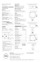
Fig. 2 Dimensions wall mounting Used materials Housing: ABS Sensor tube: PVDF 14 x 2 mm Protective cage: SS wire mesh, Adaptor: Poliamide reinforced Mode of protection: IP 65 Electrical connection Electronics: 0...70 °C Nominal temperature: 25 °C Storage: -20...+70 °C Relative humidity: 0...98 %, conden- Angled connector to DIN 43 650 for cable max. 1.5 mm², 4.5 or 7 mm Æ Weight Wall sensor: 0.25 kg Duct sensor: 0.3 kg ENVIRONMENTAL CONDITIONS Temperature limits Behaviour with mains failure Long-term effect: at standard atmo- Wall sensor: wall Duct sensor: with adaptor on duct3) or Sensor vertical...
Open the catalog to page 2All TERMYA MEDIDA Y CONTROL catalogs and technical brochures
 PMA-UNIFLEX-SG45
8 Pages
 PMA-UNIFLEX-CI45
8 Pages
 PMA-UNIFLEX-CI35
6 Pages
 PARTLOW-DataVU-7
21 Pages
 PARTLOW-MRC-5000
4 Pages
 PARTLOW-MRC-7000
6 Pages
 PARTLOW-MRC-8000
4 Pages
 PARTLOW-MRC-9000
4 Pages
 serv-rite wire
40 Pages
 SENSORES CAPACITIVOS
7 Pages

- Kiln
- Electrical cable
- Data connector
- Temperature probe
- Chamber kiln
- Electric furnace
- Metal connector
- Copper cable
- Copper electrical cable
- Resistance temperature sensor
- Pressure transmitter
- Polymer connector
- Calibration system
- Analog pressure transmitter
- Digital temperature control
- Cable sleeve
- Multi-strand cable
- Multi-wire electrical cable
- Digital indicator