
- Catalogs
- TERCESA,S.L.
- Reductor XC

Reductor XC

Reductor XC
1. Overview of X Series Worm Gearboxes
The X series worm gearboxes come in three main versions: XA (shaft-mounted), XF, and XC (motor mounting). The XF version, equipped with a bell and coupling, offers higher efficiency and flexibility, while the compact XC version is optimized for space-saving applications. Housing materials vary by size: cast iron for sizes 90, 110, and 130, and die-cast aluminum for smaller sizes. The worm shaft is made from case-hardened, ground alloy steel, and the worm wheel features a cast iron hub with a cast bronze ring. Cast iron housings are painted blue (RAL 5010), and aluminum housings are sandblasted. A hollow output shaft is standard, with numerous accessories available such as second inputs, tapered roller bearings, output flanges, extended shafts, torque limiters, torque arms, and protection kits.
2. Designation and Versions
Gearboxes are identified by input type and size, with multiple mounting positions and flange options. Detailed coding facilitates selection based on specific application requirements, including motor coupling and mounting configurations.
3. Lubrication and Mounting Positions
Except for size 130, gearboxes are supplied with synthetic PAG lubricant (ISO VG320). Specifying the mounting position at order is critical to ensure proper lubrication and performance. Smaller aluminum housings (sizes 30 to 75) have a single oil filling plug. Detailed tables specify oil quantities per size and mounting position, along with locations for filling, breather, level, and drain plugs.
4. Terminal Board Position
The terminal board position must be specified when ordering to guarantee correct electrical connection and installation orientation. Reference is made to detailed terminal board positions (PM=1; PM=2) documented on pages 33-34.
5. Technical Data and Performance Parameters
Comprehensive tables provide data for input speeds of 2800, 1400, 900, and 500 rpm across sizes 30 to 130. Key parameters include reduction ratio (Rd), rated torque (T2), power ratings (P, P1), and service factors (FS’). Maximum allowable torque (T2M) is calculated as T2 multiplied by FS’. Data covers XC and XF versions with various flange types (B5, B14) and mounting configurations. Power ratings range from fractions of a kilowatt to several kilowatts depending on size and speed. Efficiency values and moments of inertia are also provided for precise engineering calculations.
6. Additional Features and Accessories
Options include additional inputs (double extended shafts), torque limiters with through hollow shafts, torque arms, and protection kits. These enhance adaptability and safety in diverse industrial applications.
7. Torque Limiter with Through Hollow Shaft
The torque limiter protects machinery by limiting transmissible torque, integrating a friction clutch within the gearbox. It operates in an oil bath for reliability and wear resistance but is not compatible with tapered roller bearings or prolonged slipping. Calibration is externally adjustable via a self-locking ring nut compressing Belleville washers. Slipping torque varies with load conditions and decreases over time due to wear, necessitating regular calibration checks. Devices are supplied pre-calibrated to catalog torque values unless otherwise specified.
8. Technical Specifications and Dimensions
Detailed dimensional data is provided for flange types (XA, XC, XF) and IEC standards (IEC 90, 100-112, 132) across sizes 30 to 130. Parameters include shaft diameters, flange thicknesses, bolt hole sizes, and mounting dimensions with precise tolerances (e.g., j6, H7, h8). Hybrid flange combinations are possible, with PM=2 mounting recommended only if PM=1 is not feasible.
9. Calibration and Torque Testing
Periodic calibration verification is recommended, especially during the break-in phase. For applications requiring tighter accuracy, transmissible torque testing on the system is advised. Torque limiters are delivered calibrated to catalog torque values unless otherwise specified.
10. Accessories and Spare Parts
Available accessories include single and double output shafts, torque arms, protection kits, optional tapered roller bearings, hollow shafts, and torque limiters with detailed dimensional specifications. The spare parts list covers bearings, oil seals, and closed oil seals for sizes 30 to 130, with standard bearing numbers and optional tapered roller bearings available on request.
Critical Information and Best Practices
- Always specify mounting position and terminal board location when ordering to ensure correct lubrication and installation.
- Calculate maximum allowable torque using the provided service factor to prevent overloading.
- Select the appropriate gearbox version (XA, XF, XC) based on efficiency, space constraints, and motor coupling needs.
- Consult detailed technical tables for power, torque, and speed ratings to choose the correct size and configuration.
- Use available accessories to customize gearboxes for specific operational and protection requirements.
- Torque limiters must not be used with tapered roller bearings or for prolonged slipping operations.
- Regular maintenance and calibration checks of torque limiters are essential for performance and longevity.
- Hybrid flange combinations are feasible; PM=2 flange mounting is recommended only if PM=1 is not possible.
Catalog excerpts
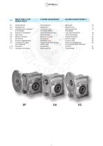
RIDUTTORIA VITE X WORM GEARBOXES Caratteristiche Designazione Lubrificazione e posizioni di montaggio Posizione morsettiera Dati tecnici Momenti d'inerzia Dimensioni Entrata suppiementare Limitatore di coppia cavo passante Accessori Lista parti di ricambio Characteristics Designation Lubrication and mounting position Terminal board position Technical data Moment of inertia Dimensions Additional input Torque limiter with through hollow shaft Accessories Spare parts list Merkmale Bezeichnung Schmierung und Einbaulage Lage des Klemmbrett Technische Daten Tragheitsmoment Abmessungen Zusatzantrieb Drehmomentbegrenzer mit durchgehender Hohlwelle Zubehor Ersatzteilliste
Open the catalog to page 1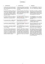
• I riduttori a vite senza fine della serie X • X series worm gearboxes are available • Die Schneckengetriebe der Serie X sind in die Versiön XA mit Welle und in the following versions : XA with shaft, sono disponibili nelle versioni alberata XF / XC mit Motoranschluß lieferbar. XF and XC suitable for motor mounting XA e con predisposizione per attacco assembling. motore XF-XC. • La versione XF (campana + giunto), ca- • The XF version (bell + joint) suits a wid- • Die Version XF (Glocke + Kupplung), die sich durch ihre zahlreichen Anwener range of applications and provides ratterizzata da una...
Open the catalog to page 2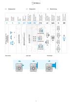
Riduttore a vite senza fine Wormgearbox Schneckengetriebe Riduttore Gearbox Getriebe Tipo entrata Input type Antriebsart Grandezza Size Größe Rapporto rid. Ratio Untersetzung Predispos.att. mot. Motor coupling Motoranschluss Posizione di mont. Mounting position Einbaulage Flangia in uscita. Output flange Abtriebsflansch Limitatore di coppia. Torque limiter Drehmomentbegrenzer Seconda entrata Additional input Zusatzantrieb Albero uscita Output shaft Abtriebswelle Braccio di reazione Torque arm Drehmomentstütze Input type
Open the catalog to page 3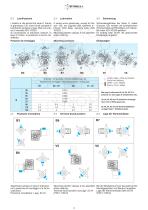
2.3 Lubrificazione I riduttori a vite senza fine serie X, tranne la grandezza 130, sono forniti completi di lubrificante sintetico a base PAG con indice di viscosita ISO VG320. Si raccomanda di precisare sempre, in fase di ordine, la posizione di lavoro desiderata. Posizioni di montaggio 2.3 Lubrication X series worm gearboxes, except for the size 130, are supplied with synthetic lubricant, PAG base, viscosity index ISO VG320. Mounting position always to be specified when ordering. Mounting positions 2.3 Schmierung Schneckengetriebe der Serie X, aulJer Groesse 130, werden mit synthetischem Schmiermittel...
Open the catalog to page 4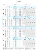
2.5 Dati tecnici 2.5 Technical data 2.5 Technische Daten 30 i 1.4 * ATTENZIONE: la coppia massima utiliz-zabile [T2M] deve essere calcolata utiliz-zando il fattore di servizio: T2M = T2 x FS' *ACHTUNG: das max. anwendbare Drehmoment [T2M] muss mit folgendem Betriebsfaktor berechnet werden: T2M = T2 x FS'
Open the catalog to page 5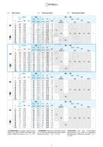
2.5 Dati tecnici 2.5 Technical data 2.5 Technische Daten 40 A 2.4 * ATTENZIONE: la coppia massima utiliz-zabile [T2M] deve essere calcolata utiliz-zando il fattore di servizio: T2M = T2 x FS' *ACHTUNG: das max. anwendbare Drehmoment [T2M] muss mit folgendem Betriebsfaktor berechnet werden: T2M = T2 x FS'
Open the catalog to page 6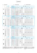
2.5 Dati tecnici 2.5 Technical data 2.5 Technische Daten 50 A 4.0 * ATTENZIONE: la coppia massima utiliz-zabile [T2M] deve essere calcolata utiliz-zando il fattore di servizio: T2M = T2 x FS' *ACHTUNG: das max. anwendbare Drehmoment [T2M] muss mit folgendem Betriebsfaktor berechnet werden: T2M = T2 x FS'
Open the catalog to page 7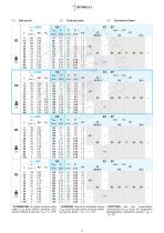
2.5 Dati tecnici 2.5 Technical data 2.5 Technische Daten 63 A 6.6 * ATTENZIONE: la coppia massima utiliz-zabile [T2M] deve essere calcolata utiliz-zando il fattore di servizio: T2M = T2 x FS' *ACHTUNG: das max. anwendbare Drehmoment [T2M] muss mit folgendem Betriebsfaktor berechnet werden: T2M = T2 x FS'
Open the catalog to page 8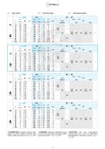
2.5 Dati tecnici 2.5 Technical data 2.5 Technische Daten 75 & 11.0 * ATTENZIONE: la coppia massima utiliz-zabile [T2M] deve essere calcolata utiliz-zando il fattore di servizio: T2M = T2 x FS' *ACHTUNG: das max. anwendbare Drehmoment [T2M] muss mit folgendem Betriebsfaktor berechnet werden: T2M = T2 x FS'
Open the catalog to page 9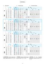
2.5 Dati tecnici 2.5 Technical data 2.5 Technische Daten 90 & 23.6 * ATTENZIONE: la coppia massima utiliz-zabile [T2M] deve essere calcolata utiliz-zando il fattore di servizio: T2M = T2 x FS' *ACHTUNG: das max. anwendbare Drehmoment [T2M] muss mit folgendem Betriebsfaktor berechnet werden: T2M = T2 x FS'
Open the catalog to page 10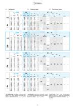
2.5 Dati tecnici 2.5 Technical data 2.5 Technische Daten 110 & 44.0 * ATTENZIONE: la coppia massima utiliz-zabile [T2M] deve essere calcolata utiliz-zando il fattore di servizio: T2M = T2 x FS' *ACHTUNG: das max. anwendbare Drehmoment [T2M] muss mit folgendem Betriebsfaktor berechnet werden: T2M = T2 x FS'
Open the catalog to page 11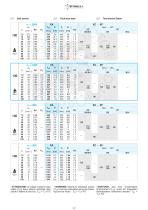
2.5 Dati tecnici 2.5 Technical data 2.5 Technische Daten * ATTENZIONE: la coppia massima utiliz-zabile [T2M] deve essere calcolata utiliz-zando il fattore di servizio: T2M = T2 x FS' *ACHTUNG: das max. anwendbare Drehmoment [T2M] muss mit folgendem Betriebsfaktor berechnet werden: T2M = T2 x FS'
Open the catalog to page 12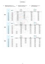
2.6 Momenti d’inerzia [Kg cm2] 2.6 Moments of inertia [Kg cm2] 2.6 Tragheitsmoment [Kg cm2](riferiti all’albero veloce in entrata) (referred to input shaft) (bez. Antriebswelle) X30
Open the catalog to page 13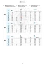
2.6 Momenti d’inerzia [Kg cm2] 2.6 Moments of inertia [Kg cm2] 2.6 Tragheitsmoment [Kg cm2](riferiti all’albero veloce in entrata) (referred to input shaft) (bez. Antriebswelle) X63
Open the catalog to page 14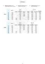
2.6 Momenti d’inerzia [Kg cm2] 2.6 Moments of inertia [Kg cm2] 2.6 Tragheitsmoment [Kg cm2] (riferiti all’albero veloce in entrata) (referred to input shaft) (bez. Antriebswelle)
Open the catalog to page 15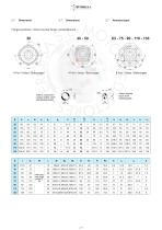
2.7 Abmessungen Flangia pendolare / Shaft-mounted flange / Aufsteckflansch30 40-50 63-75-90-110-130 4 Fori / Holes/Bohrungen 4 Fori / Holes /Bohrungen 8 Fori / Holes/Bohrungen Albero entrata Input shaft Antriebswelle Albero uscita cavo Output hollow shaft Abtriebshohlwelle
Open the catalog to page 17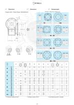
2.7 Dimensioni 2.7 DimensionsFlangia uscita / Output flange / Abtriebsflansch 2.7 Abmessungen Vista da A / View from A / Ansicht von A Tipo Type Typ * Foratura ruotata di 22.5° * Drilling turned of 22.5°
Open the catalog to page 18All TERCESA,S.L. catalogs and technical brochures
 NRA SERIE
4 Pages
 Tandem PHB
257 Pages
 RIGHT ANGLE GEARBOX RL
8 Pages
 RIGHT ANGLE GEARBOX
16 Pages
 Reductor Epicicloidal R
14 Pages
 Reductor Epicicloidal REP
22 Pages
 Reductor Ortogonal Serie K
131 Pages
 Reductor Arboles Paralelos Z
23 Pages
 Reductor Ortogonal T
33 Pages
 Reductor KC
22 Pages
 Reductor BFK
18 Pages
 Reductor SFK
18 Pages
 Réducteur Pendulaire
259 Pages
 General Catalogue 2015/2016
36 Pages
 Réducteur Planétaire
246 Pages
 Moteur a courant continu
21 Pages
 Réducteur Coaxiaux
10 Pages
 Réducteur Arbres Parallèles
23 Pages
 BEVEL HELICAL GEARBOX
33 Pages
 SFK-SRK WORM GEARBOXES
18 Pages


- Electric gearmotor
- Planetary gearbox
- Coaxial gearhead
- Precision gearhead
- Right angle gearhead
- Compact gearhead
- Gear train gear reducer
- Gearbox for industrial applications
- Transmission gearhead
- Industrial electric gearmotor
- Coaxial gearmotor
- Helical gear gearhead
- Planetary gearmotor
- Bevel gearhead
- Parallel-shaft gearhead
- Screw jack
- Conveyor gear reducer
- Aluminum gearhead
- Electric gearmotor for the food industry
- Custom-made gearhead