
- Catalogs
- TERCESA,S.L.
- Reductor KC

Reductor KC

Reductor KC
The KC worm gearboxes are designed to be lightweight with compact housing. Sizes 90, 110, and 130 are made from cast iron, while sizes 30, 40, 50, 63, and 75 are made from die-cast aluminum. The series offers versions with or without feet for versatility. The K series is available only for motor mounting (PAM) and not with a male input shaft. The worm shaft is made from case-hardened and ground alloy steel, and the worm wheel has a cast-iron hub with a cast bronze ring. Cast-iron housings are painted BLUE RAL5010, and aluminum housings are sandblasted. Standard equipment includes a hollow output shaft, with various accessories available.
The gearbox designation includes type, size, version, reduction ratio, motor coupling, mounting position, torque limiter, additional input, output shaft, and torque arm.
KC worm gearboxes, except size 130, come with PAG synthetic lubricant (ISO VG320 viscosity). Specify the mounting position when ordering. Aluminum housings for sizes 30, 40, 50, 63, and 75 have one filling plug.
Technical data includes specifications for sizes and configurations, such as input speed, output speed, torque, power, and service factors. Calculating maximum allowable torque using the service factor is crucial.
The torque limiter with a through hollow shaft limits transmissible torque to protect machinery from overloads. It operates in an oil bath for reliability and reduced wear.
Torque limiter calibration is adjusted externally by tightening a self-locking ring nut, compressing four Belleville washers. Regular calibration checks are important, especially during the running-in period, as slipping torque decreases over time.
Avoid using the device with tapered roller bearings at the output or under prolonged slipping conditions. Slipping reduces transmitted torque by about 30%. It is advisable to stop and restart to achieve initial torque settings.
Tables provide slipping torques (M2S) values based on ring nut revolutions, with a ±10% tolerance under static conditions. Dynamic conditions affect these values, with higher values for uniform load increases and lower for sudden load peaks.
The torque limiter is calibrated to the torque value specified in the T2M catalog unless otherwise ordered. The version with the torque limiter does not include output shafts. Detailed tables provide dimensions and specifications for different components.
Catalog excerpts
RIDUTTORE A VITE K WORM GEARBOXES SCHNECKENGETRIEBE KSENZA FINE SERIE K Characteristics Designation Lubrication and mounting position Terminal board position Technical data Moments of inertia Dimensions Additional input Torque limiter with through hollow shaft Accessories Spare parts list 3.3 Lubrificazione e posizioni di montaggio 3.11 Lista parti di ricambio Merkmale Bezeichnung Schmierung und Einbaulage Lage des Klemmenbrett Technische Daten Tragheitsmoment Abmessungen Zusatzantrieb Drehmomentbegrenzer mit durchgehender Hohlwelle Zubehor Ersatzteilliste
Open the catalog to page 1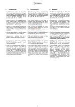
• I riduttori della serie a vite senza fine • The KC worm gearboxes are extremely • Die Schneckengetriebe der Serie KC sind äußerst leicht dank der kompakten light thanks to the compact shape of the KC si presentano estremamente leggeForm des Gehäuses. Das Gehäuse ist housing, which is in cast iron for sizes ri grazie alla forma compatta della caraus Gusseisen für Größen 90, 110 und 90, 110 and 130, in die-cast aluminium cassa in ghisa nelle grandezze 90,110 130, aus Druckgussaluminium für Gröfor sizes 30, 40, 50, 63 and 75. e 130, in alluminio pressofuso per le ßen 30, 40, 50, 63 und 75. grandezze...
Open the catalog to page 2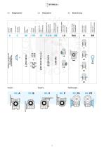
* a c 8-2 W ’g 0 d) (t O) ■S 0 C > ra C o s| S O S £ S o 3 (/) Versioni Versions
Open the catalog to page 3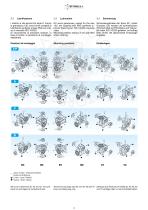
I riduttori a vite senza fine serie K, tranne la grandezza 130, sono forniti completi di lubrificante sintetico a base PAG con indice di viscosità ISO VG320. Si raccomanda di precisare sempre, in fase di ordine, la posizione di montaggio desiderata. KC worm gearboxes, except for the size 130, are supplied with PAG synthetic lubricant featuring an ISO VG320 viscosity class. Mounting position always to be specified when ordering. Schneckengetriebe der Serie KC, außer Groesse 130, werden mit synthetischem Schmiermittel auf PAG Basis und Viskosität Index ISO VG320 geliefert. Im Auftrag bitte immer...
Open the catalog to page 4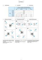
Specificare sempre in fase di ordinazio-ne la posizione di montaggio e la forma costruttiva. Posizione morsettiera v. pag. 58 (PM=1; PM=2) Mounting position always to be specified when ordering. Terminal board position see page 58 (PM=1; PM=2) Bei der Bestellung immer die gewunschte Montageposition und Bauform angeben. Lage der Klemmenkaste Seite 58 (PM=1; PM=2)
Open the catalog to page 5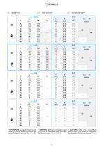
3.5 Dati tecnici 3.5 Technical data 3.5 Technische Daten 30 * m 1.2 * ATTENZIONE: la coppia massima utiliz-zabile [T2M] deve essere calcolata utiliz-zando il fattore di servizio: T2M = T2 x FS'
Open the catalog to page 6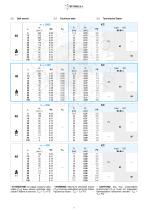
3.5 Dati tecnici 3.5 Technical data 3.5 Technische Daten 40 • El 2.0 * ATTENZIONE: la coppia massima utiliz-zabile [T2M] deve essere calcolata utiliz-zando il fattore di servizio: T2M = T2 x FS'
Open the catalog to page 7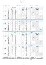
3.5 Dati tecnici 3.5 Technical data 3.5 Technische Daten 50 • El 3.4 * ATTENZIONE: la coppia massima utiliz-zabile [T2M] deve essere calcolata utiliz-zando il fattore di servizio: T2M = T2 x FS'
Open the catalog to page 8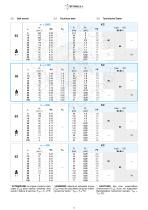
3.5 Dati tecnici 3.5 Technical data 3.5 Technische Daten 63 • El 5.7 * ATTENZIONE: la coppia massima utiliz-zabile [T2M] deve essere calcolata utiliz-zando il fattore di servizio: T2M = T2 x FS'
Open the catalog to page 9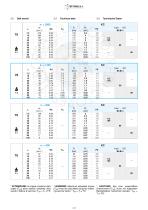
3.5 Dati tecnici 3.5 Technical data 3.5 Technische Daten * ATTENZIONE: la coppia massima utiliz-zabile [T2M] deve essere calcolata utiliz-zando il fattore di servizio: T2M = T2 x FS'
Open the catalog to page 10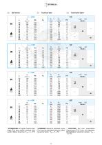
3.5 Dati tecnici 3.5 Technical data 3.5 Technische Daten 90 * m 16.4 * ATTENZIONE: la coppia massima utiliz-zabile [T2M] deve essere calcolata utiliz-zando il fattore di servizio: T2M = T2 x FS'
Open the catalog to page 11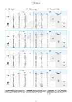
112 100 90 90 * ATTENZIONE: la coppia massima utiliz-zabile [T2M] deve essere calcolata utiliz-zando il fattore di servizio: T2M = T2 x FS' * WARNING: Maximum allowable torque [T2M] must be calculated using the following service factor: T2M = T2 x FS’ * ACHTUNG: das max. anwendbare Drehmoment [T2M] muss mit folgendem Betriebsfaktor berechnet werden: T2M = T2 x FS'
Open the catalog to page 12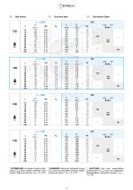
3.5 Dati tecnici 3.5 Technical data 3.5 Technische Daten 130 * m 45 * ATTENZIONE: la coppia massima utiliz-zabile [T2M] deve essere calcolata utiliz-zando il fattore di servizio: T2M = T2 x FS'
Open the catalog to page 13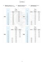
3.6 Momenti d’inerzia [Kg cm2] 3.6 Moments of inertia [Kg cm2] 3.6 Tragheitsmoment [Kg cm2](riferiti all’albero veloce in entrata) (referred to input shaft) (bez. Antriebswelle) K30
Open the catalog to page 14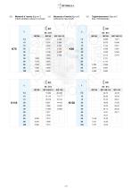
3.6 Momenti d’inerzia [Kg cm2] 3.6 Moments of inertia [Kg cm2] 3.6 Tragheitsmoment [Kg cm2](riferiti all’albero veloce in entrata) (referred to input shaft) (bez. Antriebswelle) K75
Open the catalog to page 15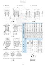
Flangia pendolare / Side cover for shaft mounting / Aufsteckflansch Albero uscita cavo Hollow output shaft Abtriebshohlwelle
Open the catalog to page 16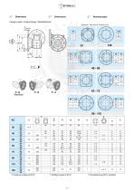
3.7 Dimensioni 3.7 DimensionsFlangia uscita / Output flange / Abtriebsflansch Vista da A / View from A / Ansicht von A * Foratura ruotata di 22.5° * Drilling turned of 22.5° * Durchbohrung 22.5° versetzt
Open the catalog to page 17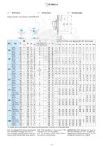
3.7 Dimensioni 3.7 Flangia entrata / Input flange / Antriebsflansch * A richiesta, solo con corpo speciale / Upon request, only with special body / Auf Wunsch nur mit speziellen Korper N.B.: Il montaggio STD di PM=2 solo quando non e possibile il montaggio STD di PM=1. N.B.: E' possibile realizzare anche tutte le com-posizioni ibride ottenibili dalle flange esistenti. N.B.: STD mounting of PM=2 only if STD mounting of PM=1 is not possible. N.B.: it is possible to create hybrid combinations with the existing flanges. ANMERKUNG: STD Montage von PM=2 nur wenn STD Montage von PM=1 unmoglich ist. ANMERKUNG:...
Open the catalog to page 18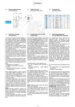
Entrata supplementare (vite bisporgente) (double extended shaft) 3.9 Limitatore di ccppia cavo passante II limitatore di coppia viene consigliato in tutte quelle applicazioni che richiedono una limitazione sulla coppia trasmissibile per proteggere I’impiantc e/o preservare il riduttore evitando sovraccarichi o urti in-desiderati quanto inaspettati. E un dispositivo con albero dotato di cavo passante, con funzionamento a frizione, ed e integrate al riduttore, presentando un ingombro limitato. Concepito per lavorare a bagno d’olio, il dispositivo risulta affidabile nel tempo ed e esente da usura...
Open the catalog to page 19All TERCESA,S.L. catalogs and technical brochures
 NRA SERIE
4 Pages
 Tandem PHB
257 Pages
 RIGHT ANGLE GEARBOX RL
8 Pages
 RIGHT ANGLE GEARBOX
16 Pages
 Reductor Epicicloidal R
14 Pages
 Reductor Epicicloidal REP
22 Pages
 Reductor Ortogonal Serie K
131 Pages
 Reductor Arboles Paralelos Z
23 Pages
 Reductor Ortogonal T
33 Pages
 Reductor XC
25 Pages
 Reductor BFK
18 Pages
 Reductor SFK
18 Pages
 Réducteur Pendulaire
259 Pages
 General Catalogue 2015/2016
36 Pages
 Réducteur Planétaire
246 Pages
 Moteur a courant continu
21 Pages
 Réducteur Coaxiaux
10 Pages
 Réducteur Arbres Parallèles
23 Pages
 BEVEL HELICAL GEARBOX
33 Pages
 SFK-SRK WORM GEARBOXES
18 Pages


- Electric gearmotor
- Planetary gearbox
- Coaxial gearhead
- Precision gearhead
- Right angle gearhead
- Compact gearhead
- Gear train gear reducer
- Gearbox for industrial applications
- Transmission gearhead
- Coaxial gearmotor
- Industrial electric gearmotor
- Planetary gearmotor
- Helical gear gearhead
- Bevel gearhead
- Parallel-shaft gearhead
- Screw jack
- Conveyor gear reducer
- Aluminum gearhead
- Electric gearmotor for the food industry
- Custom-made gearhead