
- Catalogs
- TERCESA,S.L.
- Réducteur Pendulaire

Réducteur Pendulaire

Réducteur Pendulaire
- Industrial Applications: Lists machinery and equipment used in different industries, such as cereal cookers, dough mixers, meat grinders in the food industry, and various types of mills and conveyors in metal and lumber industries.
- Gear Types and Designs: Describes different gear unit series, including double, triple, quadruple, and quintuple reduction parallel shaft gear units. It also explains the configurations for hollow and solid shafts, including options for rubber buffers and fixing elements.
- Motor Options: Details various motor configurations, including three-phase motors, explosion-proof motors, and motors with different pole numbers. It also covers motor options like brakes, thermal protection, and soft start rotors.
- Nomenclature: Provides abbreviations and meanings for terms used in gear unit descriptions, such as hollow shaft, solid shaft, flange types, and adapters.
Catalog excerpts
İÇİNDEKİLER CONTENTS
Open the catalog to page 1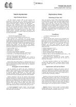
TEKNİK BİLGİLER EXPLANATORY NOTES Teknik Açıklamalar Explanatory Notes Dişli Ünitesini Seçme Selecting of Gear Unit Bir dişli ünitesini seçerken TRC üç fazlı asenkron AC motorlarını veya tek fazlı AC motorları kullanılır ve teknik olarak kıyaslanabilen motorlar için de geçerlidir. Başka motorlar kullanırken, lütfen ’e danışınız. Bir dişli ünitesini seçme ile ilgili aşağıdaki önemli ana esaslara bağlı kalınmazsa, aşırı bir yük durumunun olması muhtemeldir. Bu durumda, tüm garantiler geçersizdir. Şüpheli durumda, lütfen dişli ünitesi tasarımını kontrol etmek için birlikte çalışabileceğiniz teknik...
Open the catalog to page 2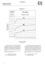
SERVİS FAKTÖRÜ SERVICE FACTOR Diyagram - 1 Operasyon saat / gün Servis Faktörü fB Service Factor f B Start sayısı / Saat Cycle / Hour Diyagram 1, günlük çalışma zamanına bağlı gerekli minimum servis faktörü f B min , ‘Z’ saatteki çevrimleri, ve uygulama yükü sınıflandırması ‘U’, ‘M’, ‘H’ gösterir. Çalışma düzgünlüğüne ve kütle hız faktörüne bağlı olarak, üç yük sınıflandırması belirlenmiştir. Hareket ettiren makineden gelen etkiler çalışma düzgünlüğü sınıflandırmasında tanımlanırken, kütle hız faktörü en fazla olan yük üzerinde etkili olur. Diagram 1 shows requiring minimum service factor depend...
Open the catalog to page 3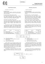
TEKNİK BİLGİLER EXPLANATORY NOTES Dişli Ünitesini Seçme Selecting a Gear Unit Operation classification; a) Düzgün çalışma Küçük karıştırıcılar, asansörler, konveyörler, montaj bantları, doldurma makinaları, bantlı konveyörler, temizleme makinaları, fanlar, test makinaları. a) Uniform application Small agitators, elevators, conveyors, assembly belts,filling machines, conveyor belts, cleaning machines, fans, testing machines. b) Yumuşak şoklar, düzgün olmayan çalışma b) Moderate shocks, non-uniform application Heavy conveyors belts, mills, stall dunging machines, crane traveling mechanisms, bending...
Open the catalog to page 4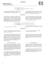
TEKNİK BİLGİLER EXPLANATORY NOTES Dişli ünitesini doğru şekilde seçtiğinizde, çıkış ve hız genel açıklamalarından alınan servis faktörü fB , diyagram 1’e göre minimum servis faktörü f B min ’den büyük veya eşittir . If the selecting gear unit is right, service factor which is taken from selection of gear motors table, must be greater than minimum service factor f B min which is taken from diagram-1 (see page 4) according to types of load. f B ≥ f Bmin Helisel, parallel mil ve helisel konik dişli ünitelerinde herbir kademe için çok yüksek bir seviyede verimlilik vardır ( herbir kademe için yaklaşık...
Open the catalog to page 5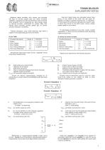
TEKNİK BİLGİLER EXPLANATORY NOTES Axial and radial forces are calculated where force acting on the middle of the shaft end see page 39. Direction of rotation is played important role in calculation. For that reason this forces are calculated and result’s value is found from forces to the shaft worse. Hence, please explain details in your orders. Listelenen radyal kuvvetler, milin ucunun orta kısmında etki eden bir kuvvete karşılık gelir. İzin verilen kuvvetleri saptarken, uygulanan kuvvetin hiç istenmeyen yönü ve dönme yönü varsayıldı. Tam bir hesaplama için, daha yüksek radyal ve eksenel kuvvetler...
Open the catalog to page 6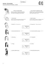
RADYAL YÜK HESABI CALCULATION OF RADIAL LOADS RADYAL YÜKLERİN HESABI Radyal yük FR (N)' nun hesaplanmasında gerekli tahrik momenti Ma (Nm), kasnak veya dişli çapı D (mm) olmak üzere aşağıdaki formüller kullanılır. Radial load FR (N) is calculated with the following equations where required moment Ma (Nm) and hoop or gear diameter D (mm) is Çalışma sırasında oluşan sapmalar kaplinin güvenlik sınırları içerisinde ise kuvvetler ihmal edilebilir. If elastic coupling is working in its reliable working area, the overhung loads can be neglected. 2 - Düz Dişli ( 20° kavrama açılı ) CALCULATION OF OVERHUNG...
Open the catalog to page 7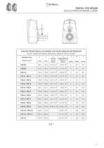
RADYAL YÜK HESABI CALCULATION OF RADIAL LOADS ÇIKIŞ ŞAFTINDAKİ RADYAL VE EKSENEL YÜK HESAPLAMALARI İÇİN DEĞERLER VALUE TABLE FOR RADIAL AND AXIAL LOADS AT OUTPUT SHAFT Redüktör Tipi Gearbox Type
Open the catalog to page 8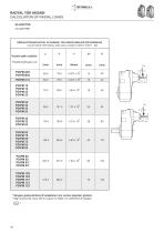
RADYAL YÜK HESABI CALCULATION OF RADIAL LOADS - W ADAPTÖR - W ADAPTER GİRİŞ ŞAFTINDAKİ RADYAL VE EKSENEL YÜK HESAPLAMALARI İÇİN DEĞERLER VALUE TABLE FOR RADIAL AND AXIAL LOADS AT INPUT SHAFT f=0 Paralel şaftlı redüktör Parallel shaft gear unit PD\PM 12 PD\PM 13 PD\PM 23 PD\PM 33 PD\PM 22 PD\PM 32 PD\PM 43 PD\PM 53 PD\PM 42 PD\PM 52 PD\PM 63 PD\PM 62 PD\PM 72 PD\PM 63* PD\PM 73 PD\PM 83 PD\PM 93 PD\PM 82 PD\PM 92 PD\PM 83* PD\PM 93* PD\PM 102 PD\PM 103 PD\PM 112 PD\PM 113 PD\PM 123 * Simgesi güçlendirilmiş W adaptörleri için verilen değerleri gösterir. * Sign shows that value which is given on...
Open the catalog to page 9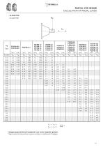
RADYAL YÜK HESABI CALCULATION OF RADIAL LOADS - W ADAPTÖR PD\PM 12 PD\PM 13 PD\PM 23 PD\PM 33 PD\PM 22 PD\PM 32 PD\PM 43 PD\PM 53 PD\PM 62 PD\PM 72 PD\PM 63* PD\PM 73 PD\PM 83 PD\PM 93 PD\PM 42 PD\PM 52 PD\PM 63 PD\PM 82 PD\PM 92 PD\PM 83* PD\PM 93* PD\PM 102 PD\PM 103 PD\PM 112 PD\PM 113 PD\PM 123 * Simgesi güçlendirilmiş W adaptörleri için verilen değerleri gösterir. * Sign shows that value which is given on table, for reinforced W adapter.
Open the catalog to page 10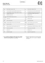
KISALTMALAR ABBREVIATIONS = Servis Faktörü (Mamax / Ma) = Çıkış tarafındaki müsaade edilebilir eksenel yük [ kN ] = Permissible axial load at the output side [ kN ] = Çıkış tarafındaki, milin orta noktasına etkiyen müsaade edilebilir radyal yük [ kN ] = Permissible overhung load at the output side, force acting at the shaft's midpoint [ kN ] = Gear units total ratio toplam = Dişli ünitesindeki toplam tahvil oranı = Service factor (Mamax / Ma) Mamax = Müsaade edilebilir maksimum çıkış momenti [Nm] Mamax = Max. permissible output torque [Nm] = Mamax referans alınarak hesaplanan güç [kW] = Calculated...
Open the catalog to page 11All TERCESA,S.L. catalogs and technical brochures
 NRA SERIE
4 Pages
 Tandem PHB
257 Pages
 RIGHT ANGLE GEARBOX RL
8 Pages
 RIGHT ANGLE GEARBOX
16 Pages
 Reductor Epicicloidal R
14 Pages
 Reductor Epicicloidal REP
22 Pages
 Reductor Ortogonal Serie K
131 Pages
 Reductor Arboles Paralelos Z
23 Pages
 Reductor Ortogonal T
33 Pages
 Reductor XC
25 Pages
 Reductor KC
22 Pages
 Reductor BFK
18 Pages
 Reductor SFK
18 Pages
 General Catalogue 2015/2016
36 Pages
 Réducteur Planétaire
246 Pages
 Moteur a courant continu
21 Pages
 Réducteur Coaxiaux
10 Pages
 Réducteur Arbres Parallèles
23 Pages
 BEVEL HELICAL GEARBOX
33 Pages
 SFK-SRK WORM GEARBOXES
18 Pages


- Electric gearmotor
- Planetary gearbox
- Coaxial gearhead
- Precision gearhead
- Right angle gearhead
- Compact gearhead
- Gear train gear reducer
- Gearbox for industrial applications
- Transmission gearhead
- Industrial electric gearmotor
- Coaxial gearmotor
- Helical gear gearhead
- Planetary gearmotor
- Bevel gearhead
- Parallel-shaft gearhead
- Screw jack
- Conveyor gear reducer
- Aluminum gearhead
- Electric gearmotor for the food industry
- Custom-made gearhead