
- Catalogs
- Terasaki Electric Ltd
- Terasaki - Air Circuit Breaker

Terasaki - Air Circuit Breaker

Terasaki - Air Circuit Breaker
This section highlights the critical importance of following safety protocols when handling the Air Circuit Breaker (ACB). Safety notices are categorized into 'DANGER' and 'CAUTION' based on hazard severity. Key points include avoiding standing under a suspended ACB, ensuring electrical work is performed by qualified personnel, and preventing foreign materials from entering the ACB to avoid malfunctions or fires.
Upon receipt, verify that the ACB and its accessories match the order and are undamaged. Transportation precautions include securing the ACB properly during transport and avoiding shocks and vibrations. Storage recommendations emphasize the need for a dry, clean environment to prevent condensation and corrosion.
Installation should be conducted by competent individuals, ensuring the ACB is not placed in environments with extreme conditions that could lead to malfunctions or fires. It is crucial to isolate power sources before commencing work to prevent electric shock.
This section details the procedures for charging, opening, and closing operations of the ACB. It includes instructions for draw-out and insertion operations, emphasizing the importance of securing the draw-out cradle to prevent accidents.
Specifications and settings for the OCR are provided, focusing on ensuring adjustments are made by qualified personnel to prevent malfunctions. The section also covers the importance of returning setting switches to their original positions post-testing.
Regular maintenance and inspection are crucial for the ACB's longevity and safety. This section outlines procedures for inspecting and replacing parts, emphasizing the need for competent personnel to perform these tasks to avoid injuries and ensure proper functioning.
Troubleshooting flowcharts are provided to assist in diagnosing and resolving common issues with the ACB.
The document references several standards including IEC60947-2, EN60947-2, AS3947-2, JIS C8201-2, NEMA SG-3, and ANSI C37.13, which pertain to the specifications and operational guidelines for circuit breakers.
Temperature ratings are provided for various ambient conditions, indicating the permissible current ratings at different temperatures (40°C, 45°C, 50°C, 55°C, and 60°C). These ratings are crucial for ensuring the circuit breaker operates safely under varying environmental conditions.
The document details the components of an Air Circuit Breaker (ACB), including the breaker body, draw-out cradle, ON/OFF buttons, indicators, charging handle, and various terminals. Each part is described with its function, such as the overcurrent release (OCR) which protects against overcurrent by tripping the breaker.
Figures and tables illustrate the circuit diagrams and terminal functions. The document specifies the ratings for operation power supply, shunt trip device, undervoltage trip device, auxiliary switches, and position switches. These ratings ensure compatibility with different voltage and current requirements.
Operational procedures include charging and opening operations with safety warnings. It emphasizes the importance of adhering to voltage ranges and operational limits to prevent damage or hazards. The document advises against exceeding 15 continuous open/close operations without a pause to avoid motor burnout.
Safety warnings highlight the risks of electric shock and burns from arc gases. Users are cautioned to avoid contact with live parts and to maintain safe distances from arc gas vents during operation.
The document discusses Air Circuit Breakers (ACBs) available in two types based on the closing spring charging method and remote operation capability: manual charging and motor charging types. Manual charging requires manual operation, while motor charging allows both manual and motorized operation.
ACBs can only be closed when the closing springs are charged. Manual charging involves using a handle to pump until the charge indicator shows "CHARGED." Motor charging activates automatically when the operation voltage is applied, taking less than 10 seconds.
Conditions for closing include a "CHARGED" indicator, correct position indicator, absence of the draw-out handle, and specified voltage supply. Manual closing involves pressing the ON button, while electrical closing uses an ON switch.
Manual opening requires pressing the OFF button, and electrical opening involves an OFF switch activating a trip device. Both methods result in the ACB tripping open.
Figures illustrate the motion of charging and ON-OFF mechanisms, detailing the rotation and engagement of various components during manual and electrical operations.
The draw-out type ACB consists of a breaker body and cradle, allowing inspection without removing wiring. The breaker can be moved to four positions: CONN., TEST, ISOLATED, and Removed. Safety precautions include securing the cradle and avoiding contact with live parts.
Steps for moving the breaker body between positions involve opening the ACB, loosening bolts, unlocking levers, and using a draw-out handle. Specific instructions are provided for each position transition.
Warnings include avoiding live terminal contact, ensuring secure mounting, and proper handling to prevent injury or equipment damage. The importance of tightening fixing bolts to prevent malfunctions is emphasized.
- Breaker Body and Draw-out Rail: The document describes the placement of the breaker body on the draw-out rail, highlighting the components involved such as the breaker body rollers and draw-out cradle.
- Contact Status of Switches: Tables detail the contact status of auxiliary and position switches, indicating the status of a-contact and b-contact in various states such as ON, OFF, CONN., TEST, ISOLATED, and Removed.
- Locking Procedures: Procedures for locking various components to prevent unauthorized operation.
- Overcurrent Release (OCR): The OCR for type AR ACBs is a multi-functional device with a built-in microprocessor. It detects faults and sends trip signals or alarms. The OCR uses root mean square sensing for various functions and is available in three types: AGR-11L, AGR-11R, and AGR-11S, each with specific characteristics for different applications.
- OCR Specifications and Settings: Detailed specifications for the AGR-11 OCR types, outlining the setting procedures and emphasizing the need for competent personnel and appropriate tools to avoid malfunctions.
- Characteristic Curves: Figures illustrate the characteristic curves for the AGR-11L and AGR-11R OCR types, showing the relationship between current and time for different trip functions.
- Tightening Torque: For relay base mounting screws, the torque is specified between 2.7 - 3.5 N·m. For MHT mounting screws, the torque is 1.3 - 1.7 N·m.
- Relay Base Removal: Steps include unscrewing mounting screws, raising the relay base, and removing it from the breaker body. Ensure the ground terminal is also removed.
- Magnet Hold Trigger (MHT) Replacement: Involves removing the OCR and relay base, unscrewing MHT mounting screws, and disconnecting the hand connector.
- Auxiliary Switch Replacement: Requires loosening cover fixing screws, removing mounting screws, and applying molybdenum grease during reinstallation.
- System Alarm LED On: Check manual charging, operation voltage, and control circuit. Contact Terasaki if unresolved.
- Closing Impossible: Verify manual and electrical closing, operation mechanism, and control circuit. Adjust voltage and check contacts as needed.
- Opening Impossible: Ensure manual and electrical opening is possible, check operation voltage, and inspect control circuit.
- Overheat Issues: Confirm ambient temperature and load current are as specified, and check OCR settings and main circuit contacts.
- Function: Prevents panel opening when ACB is closed or in certain positions. Operable only when ACB is open and isolated.
- Adjustment: Involves checking handle shutter position and adjusting the plate if necessary.
- Types: Applicable to various breaker types such as AR2, AR3, and AR4.
- Installation Precautions: Must be performed by qualified personnel, avoiding high temperature and humidity areas.
- Operation: Interlock is enabled in connected position; disabled in test, isolated, or draw-out positions.
- Tighten components to the specified torque.
- Ensure the distance between the support and the lever is within the specified range; adjust if necessary.
- For draw-out type ACBs, insert the ACB bodies into the chassis to the connected position before turning them on. For fixed type ACBs, unlock the ACB.
- Verify the main circuit is not energized before checking the operation of the ACBs. Avoid touching the interlock during operation.
- Published in June 2002.
- Revised in November 2002, April 2003, March 2004.
- The contents of this manual may change without notice.
- Recycle paper used.
Catalog excerpts
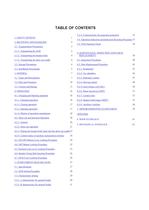
5-3-3. S characteristic for generator protection35 1. SAFETY NOTICES1 5-4. Operation Indication and Indication Resetting Procedure37 2. RECEIVING AND HANDLING3 5-5. OCR Function Check38 2-1. Transportation Precautions3 2-1-1. Transporting the ACB3 6. MAINTENANCE, INSPECTION AND PARTS 2-1-2. Transporting the breaker body4 REPLACEMENT39 2-1-3. Transporting the draw-out cradle4 6-1. Inspection Procedures40 2-2. Storage Precautions4 6-2. Parts Replacement Procedure43 2-3. Installation Precautions5 6-2-1. Preparation43 3. GENERAL7 6-2-2. Arc chambers46 3-1. Types and Descriptions7 6-2-3. Stationary...
Open the catalog to page 2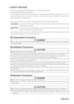
Thank you for purchasing the TERASAKI AR-series Air Circuit Breaker (TemPower2).This chapter contains important safety information. Be sure to carefully read these safety notices, instruction in this manual, and other documents accompanying the Air Circuit Breaker (hereinafter referred to as the ACB) to familiarize yourself with safe and correct procedures or practices before installing, operating, or servicing the ACB.In this manual, safety notices are divided into DANGERӔ and CAUTIONӔ according to the hazard level: DANGER : A danger notice with this symbol indicates a potentially hazardous...
Open the catalog to page 3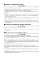
Repeated open/close operation by the motor charging mechanism without pause should not exceed 15 times. If repeatedcontinuous open/close operation is inevitable, a pause of at least 20 minutes should be provided after the repetitions of 15times. Otherwise, a spring charging motor may be burnt out. Do not bring your hand or face close to arc gas vent of the arc chamber while the ACB is closed. Otherwise, a burn mayresult from high-temperature arc gas blowing out of the arc gas vent when the ACB trips open. If the ACB trips open automatically, remove the cause of tripping operation before re-closing...
Open the catalog to page 4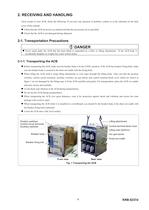
Upon receipt of your ACB, check the following. If you have any question or problem, contact us at the indicated on the backcover of this manual. Check that the ACB received is as ordered and that the accessories are as specified. Check that the ACB is not damaged during shipment. > Never stand under the ACB that has been lifted or suspended by a lifter or lifting attachments. If the ACB body isaccidentally dropped, its weight may cause serious injury. > Before transporting the ACB, make sure the breaker body is in the CONN. position. If the ACB has breaker fixing bolts, makesure the breaker body...
Open the catalog to page 5
Use an optional lifter or lifting plate to transfer the breaker body. When transporting the breaker body on a lifter, move the lifter with the lifter fork held at the lowest possible position. Take care not to exert forces on the front cover and the control circuit contacts shown in Fig. 2 . Otherwise, a deformation or damage mayresult. Lifting plate Front coverControl circuitcontact Front viewRear viewFig. 2 Transporting the breaker body > When transporting the draw-out cradle, hold it using lifting attachments or wire ropes through the lifting holes or carry it by the portions(4 points) marked...
Open the catalog to page 6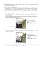
Use the receptacles shown in Table 2 to make connections with plug-in tab terminals (#187) of position switches, controlcircuit terminals, and auxiliary switches. Table 2 Receptacles for #187 tab terminals Wire thickness (mm > 2 )AWGRecommended terminalsApplicable crimp toolManufacturer 0.75 - 1.2518 - 16TMEDN480509-FA 214TMEDN480520-FANH-32NICHIFU The following procedure makes it easy to make connections with plug-in tab terminals (#187) of position switches, controlcircuit terminals, and auxiliary switches. (1) Draw out the breaker body to the removed position, and remove it using an optional...
Open the catalog to page 8
6 ON-OFF indicator Front cover > 19 7 Charge indicator ON-OFF cycle counter > 16 OFF button > 4 8 Charging handle ON-OFF button cover > 15 Lock-in-OFF plate > 14 5 ON button > 15 ON-OFF button cover Overcurrent release (OCR) > 18 OCR cover > 17 20 Rating nameplate > 9 Position indicatorDraw-out handle insertion hole Position padlock lever > 13 Release button > 12 51 Draw-out handle Ground terminalM8 ta > 11 1 37 39 Control terminal block cover Control circuit terminal > 38 49 Lifting hole (20mm) Specification nameplate > 40 Cover fixing screw Control circuit contact > 25 41 Auxiliary switches...
Open the catalog to page 12
1ACB Consists of breaker body > 3 and draw-out cradle > 2 . > 2 Draw-out cradle Comes with main circuit terminals > 48 , control circuit terminals > 38 , auxiliary switches > 41 , and positionswitches > 37 . > 3 Breaker body Contains the ON-OFF mechanism, the closing coil the tripping device, and overcurrent release > 19 . > 4 OFF button Push to open the ACB. > 5 ON button Push to close the ACB. > 6 ON-OFF indicator Shows OFFӔ when the ACB is open and ONӔ when it is closed. > 7 Charge indicator Shows CHARGEDӔ when the closing springs are charged and DISCHARGEDӔ when it is released. > 8 Charging...
Open the catalog to page 13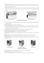
37 Position switches (optional) Indicate the present breaker body position: CONN., TEST, ISOLATED or INSERTED. Theposition switches are available in 2C or 4C configuration. Connections to the position switches are made through #187 plug- in tab terminals (standard) or M4 screws. > 38 Control circuit terminals Allow connections of external control wire to the control circuits. Wire connections are madethrough #187 plug-in tab terminals (standard) or M4 screw terminals. Fig. 8 shows the #187 tab terminals and M4 screwsterminals. #187 tab terminalsM4 screw terminalsFig. 8 Control circuit terminals...
Open the catalog to page 14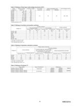
Auxiliary switches Voltage (V)Resistive load(A)Inductive load(A) *1Resistive load(A)Inductive load(A) *2Resistive load(A)Inductive load(A) *2 For general feederFor microloadPosition switches AC100 - 250550.10.1116 AC251 - 50055---- DC8----106 DC30110.10.165 DC125----0.60.6 DC250----0.30.3 DC125 - 25011---- > *1: AC cosи 0.3, DC L/R 0.007*2: AC cos 0.6, DC L/R 0.01*3: Min. applicable load: DC5V/1 mA Rated contact current (A) Individual indication Voltage (V)Resistive load (A)Inductive load (A)*1Resistive load (A)Inductive load (A)*2Resistive load (A)Inductive load (A)*2 Group indicationLong-time...
Open the catalog to page 17All Terasaki Electric Ltd catalogs and technical brochures
 TemBreak2
68 Pages
 Group starter panel model : GS22
12 Pages
 HS21
HS2120 Pages
 TZS Series Earth Leakage Relays
195 Pages
 Low Voltage Breakers
36 Pages


Archived catalogs
 TemDin Miniature Circuit Breaker
107 Pages
 Breaking Contacts Brochure
8 Pages

- Monitoring relay
- Current circuit breaker
- Voltage circuit breaker
- Single-pole circuit breaker
- DIN rail monitoring relay
- Thermal-magnetic circuit breaker
- Monitoring control system
- AC circuit breaker
- Molded case circuit breaker
- DIN rail circuit breaker
- Compact circuit breaker
- Multipole circuit breaker
- Tripolar circuit breaker
- Bipolar circuit breaker
- Current monitoring relay
- Low-voltage circuit breaker
- Motor control system
- Air-operated circuit breaker
- Engine control system