HS21
1 /20Pages

HS21
1 /20Pages
Catalog excerpts

Medium voltage, arc-proof, air-insulated, metal-clad switchgear and controlgear
Open the catalog to page 1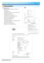
• Medium voltage switchgear for marine and • Full type approval • Type tested in accordance with IEC 62271-200 • Metal-clad construction • Independently arc-fault tested • Circuit breaker with safety metal shutter • Option of air insulated bus bars • Safety mechanical interlocks • Front service operation • Circuit breaker insertion and withdrawal with the front panel door closed • Making current earthing switch • Intelligent circuit monitoring devices Type Approval Certificate Extension This is to certify that Certificate No. 03/10027(El) for the undc-rnoted products is extended and renumbered...
Open the catalog to page 2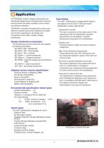
All TERASAKI medium voltage switchboards are specifically designed and manufactured to meet the environmental and safety conditions of the marine TERASAKI's reputation throughout the marine and offshore industry ensures that reliability and safety are of prime importance in the design and manufacture of the HS21 medium voltage Design standards incorporated The switchboard and the instrument have applied • I EC 60255 : electrical measuring and protection • J EC 1201 : zero phase transformer Adapted various marine classification • American Bureau of Shipping (ABS) • Bureau Veritas(BV) • Lloyds...
Open the catalog to page 3
General specification Basic specifications and panel size of 7.2 kV and 12 kV are the same (Refer to the following pages for panel size) Miniaturization rather than a conventional switchboard Abundant prepared optional equipment Type HS21-1 Standard conformance Classification Rating Rated voltage Rated frequency Rated power frequency withstand voltage Rated lightning impulse withstand voltage Rated short time withstand current Rated peak withstand current Internal arc withstand current Construction Switchgear construction Metal-clad Low voltage compartment High voltage compartment Optional equipment...
Open the catalog to page 4
Dimensions Basic panel design (example) w H2 : With open pressure relief flap Panel type Generator panel Feeder panel Incoming panel GPT panel Motor panel Soft start motor panel Bus-tie panel 1 1) Bus riser & GPT panel Sync panel Notes 1) LNG vessel only 2) Container vessel only
Open the catalog to page 5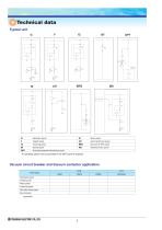
Technical data Typical unit
Open the catalog to page 6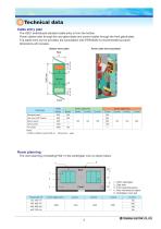
Technical data Cable entry plan The HS21 switchboard standard cable entry is from the bottom. Power cables enter through the rear gland plate and control cables through the front gland plate. Top cable entry can be provided, but consultation with TERASAKI is recommended as panel dimensions will increase. Bottom entry cable Power cable entry (example) Panel type Power cable entry B(mm) Bus-tie panel Synch panel Notes 1) Refer to 650mm panel width on Control cable entry Dimensions page Room planning The room planning of installing HS21 in the switchgear room is shown below. 5 D 1...HS21 switchgear...
Open the catalog to page 7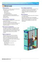
Metal-clad Compartments Each section of the HS21 metal-clad switchboard is separated into four compartments. Circuit breaker Main bus bar Cable terminations Low voltage equipment To withstand internal arc faults, segregation between compartments is achieved by the use of metal partitions. See picture below. The upper and lower low voltage compartments are located above and below the circuit breaker compartment. Cables routed through the circuit breaker compartment are protected by metal shielding. Panel partitions The compartment between each panel is divided by the metallic partition. Since...
Open the catalog to page 8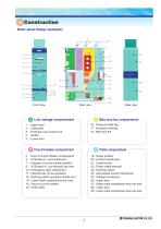
Construction Basic panel design (example) Front view Side view 16 : Pressure relief flap 17 : Insulation bushing 18 : Main bus bar : Upper door : Instrument : Protection and control unit : Switch : Lower door Rear view Circuit breaker compartment 5 : Door of circuit breaker compartment 6 : VCB draw-in / out handle port 7 : Indicator of circuit breaker position 8 : VCB draw-in / out interlock key hole 10 : Emergency open mechanism 11 : Interlock key for de-excitation 12 : Earthing switch operating handle port 13 : Lower cable compartment door key 14 : Vacuum circuit breaker 15 : VCB cradle Cable...
Open the catalog to page 9
Product description Pressure relief flaps Top panel To relieve pressure during an internal arc fault, pressure relief flaps are provided on the circuit breaker, bus bar and cable compartments at the positions shown. Pressure relief flaps Insulation bushing To maintain electrical characteristics and mechanical strength the three-phase single molding insulation bushings are manufactured using high-grade epoxy resin material. Insulation bushing Specification Rated voltage Rated power frequency withstand voltage Rated lightning impulse withstand voltage Over current strength VCB (VCT) cradle The...
Open the catalog to page 10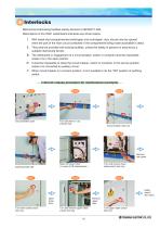
Interlocks Mechanical interlocking facilities satisfy demand of IEC62271-200. Descriptions of the HS21 switchboard interlocks are shown below. !. With metal-clad compartmented switchgear and controlgear, door should only be opened when the part of the main circuit contained in the compartment being made accessible is dead. @. They shall be provided with locking facilities, unless the safety of persons is assured by a suitable interlocking device. #. The withdrawal or engagement of a circuit breaker, switch or contactor shall be impossible unless it is in the open position. $. It shall be impossible...
Open the catalog to page 11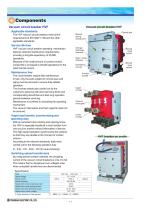
Components Vacuum circuit breaker HVF Vacuum circuit breaker HVF Applicable standards Manual spring charge port The HVF vacuum circuit breakers meet all the requirements of IEC 62271-100 and the other applicable standards. Control jack Service life time Charge / discharge indicator HVF vacuum circuit breaker operating mechanism features reduced maintenance requirements, providing a long-life expectancy of 30,000 operations. Because of the small amount of contact erosion, contact life is increased to 20,000 operations for the rated normal current. Open / close indicator Operations counter Maintenance...
Open the catalog to page 12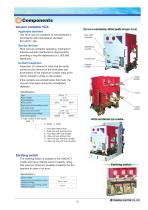
Components Vacuum contactor HCA Vacuum contactor HCA (with single fuse) Applicable standard The HCA vacuum contactor is manufactured in accordance with international standard IEC 62271-106. Service life time Operations counter HCA vacuum contactor operating mechanism features reduced maintenance requirements, providing a long-life expectancy of 1,000,000 operations. Control jack Contact inspection Position handle Inspection of contacts for wear can be easily carried out by removal of the front plate and examination of the maximum contact wear point (2mm) marked in white on the contact. Upper...
Open the catalog to page 13All Terasaki Electric Ltd catalogs and technical brochures
 TemBreak2
68 Pages
 Group starter panel model : GS22
12 Pages
 TZS Series Earth Leakage Relays
195 Pages
 Low Voltage Breakers
36 Pages


Archived catalogs
 TemDin Miniature Circuit Breaker
107 Pages
 Breaking Contacts Brochure
8 Pages
 Terasaki - Air Circuit Breaker
70 Pages

- Monitoring relay
- Current circuit breaker
- Voltage circuit breaker
- Bourn And Koch single-pole circuit breaker
- DIN rail monitoring relay
- Monitoring control system
- Thermal-magnetic circuit breaker
- AC circuit breaker
- DIN rail circuit breaker
- Molded case circuit breaker
- Compact circuit breaker
- Multipole circuit breaker
- Tripolar circuit breaker
- Bipolar circuit breaker
- Current monitoring relay
- Low-voltage circuit breaker
- Motor control system
- Air-operated circuit breaker
- Earth-leakage monitoring relay