

RFCVBS/CVBS Style Reverse Bayonet Connectors
RFCVBS/CVBS Style Reverse Bayonet Connectors
The document highlights the significance of electrical connectors in railway applications, focusing on quality and reliability. Van-System, an Italian company, has been providing customized connector solutions since 1985, tailored to specific application requirements.
Van-System's connectors adhere to Mil C 5015 specifications, offering both threaded and bayonet couplings. The company also provides modified designs to enhance performance and meet unique customer needs.
The document describes various connector series such as CVBS, CVBSG, and GVJ, each tailored for specific railway applications. These connectors feature bayonet locking systems, high resistance to vibrations and shocks, and a variety of shell sizes and contact arrangements.
- Electrical Characteristics: Detailed specifications for contact electrical characteristics, insulation, and rated voltage are provided.
- Connector Shells: Information on shell types, materials, finishes, and dimensions is included, along with compatibility tables.
- Contact Types: Options for male and female crimp contacts, coaxial contacts, and thermocouple contacts are available.
Van-System offers comprehensive services from initial technical data collection to the development of specifications, drawings, prototypes, and pre-series production, ensuring quick response to customer demands and rapid delivery.
The document lists various accessories for connectors, such as caps, gaskets, and cable clamps, along with tools for contact crimping. Safety features and standards are also highlighted.
Van-System's connectors are particularly suited for railway applications due to their robust design and adaptability to harsh conditions. The company's commitment to quality and customer service ensures reliable and efficient solutions for electrical connections in the railway sector.
The document outlines features of connector series such as oversized shells, a 5 key/keyway polarization system, and a coupling nut with rubber coating for protection against accidental drops. The GVJ and CVBSG series are highlighted, with the latter offering enhanced protection with rubber-coated shells.
Values are provided for usage at 20°C, noting that increased temperatures reduce contact conductivity and applicable current. The material of the insert must be chosen based on both ambient and induced temperatures. The document advises consulting the Sales Office for uncertainties.
Values are valid at sea level and in clean environments. Pollution from metallic or other impurities must be considered. Contacts with standard termination should match the AWG section wires.
The document provides a table of operating and test voltages, emphasizing safety measures for voltages exceeding 50V towards earth, as per CEI 23, IEC 309-1, BS 2618, and VDE 0100 standards.
Crimp contacts are commonly used in railway applications, available in copper alloy with silver or gold finishes. They are machined for precision and resistance to vibration. Various contact sizes and engagement/disengagement forces are detailed, with specific codes for different finishes.
These are used for wire sections smaller than contact termination, available in silver or gold finishes. Custom versions can be designed for different wire sections.
Designed for size 12, 8, 4, and 0 contact cavities, the document suggests consulting the Sales Office for optimal choices. An instruction manual and tools are available for proper assembly.
- R Connector Class: Suitable for single wire connections without strain relief, ideal for applications requiring minimal longitudinal space. Watertightness is ensured by the grommet, necessitating compatibility with wire diameters. Accessories may not be available in all sizes; consult the Sales Office for availability.
- AG, G, G2 Connector Classes: Designed for heat shrink tubing applications. AG class features a one-piece backshell without a grommet, G class includes a grommet, and G2 class has a two-piece backshell with a nut for tightening and internal serration to prevent rotation. Accessories availability should be confirmed with the Sales Office.
- ASB1, SB1 Connector Classes: Intended for multicore jacketed shielded cables, equipped with MS3057…C type cable-clamp. ASB1 class lacks a grommet, while SB1 class includes one. Accessories may not be in stock for all sizes; check with the Sales Office.
- GV, SB Connector Classes: Feature a special backshell for shield hose and heat shrink tubing termination, with a conical protection spring. GV class has a one-piece backshell without a grommet, and SB class includes a grommet and internal serration. Accessories availability should be verified with the Sales Office.
- AWN, WN Connector Classes: Equipped with a gasket and iris spring for mechanical strain relief and watertightness. AWN class is without a grommet, while WN class includes one. Accessories may not be available in all sizes; consult the Sales Office.
- AMK, MK Connector Classes: Include a gasket and iris spring for connecting multicore jacketed cables, with an additional gasket for watertightness. AMK class lacks a grommet, while MK class includes one. Accessories availability should be confirmed with the Sales Office.
- Shell sizes and dimensions are provided for each connector class, with specific measurements for maximum and minimum dimensions, clamping ranges, and maximum L1 lengths.
- Tables detail the dimensions in millimeters for various shell sizes, including ØB, ØD, and L1 measurements.
- Consult the Sales Office for the availability of accessories and specific connector configurations.
- Ensure compatibility of wire diameters with grommet sealing ranges for optimal performance.
1. General Overview:
The document provides detailed specifications for various connector classes within the GVJ and CVBSG series. These connectors are designed with different features such as backshells, grommets, and sealing O-rings to ensure watertightness and cable retention.
- DA and RA Classes: These connectors come with a backshell and are available with straight or 90° configurations. The DA class includes a waterproof O-ring, while the RA class adds a grommet for enhanced sealing.
- AC and ACF Classes: Similar to the DA and RA classes, these connectors are equipped with a backshell and waterproof O-ring. The ACF class includes a grommet for additional sealing.
- DAM and RAM Classes: These connectors feature a rubber-coated backshell and strain relief, ensuring cable retention and watertightness through a conical gasket and metal cone. The RAM class includes a grommet.
- AWN and WN Classes: These connectors provide cable retention and watertightness using a gasket and iris spring. The WN class includes a grommet.
The document specifies that the backshells are available with internal PG, Metric, or GAS threads suitable for various glands or conduit adapters. Customers are advised to consult the sales office for available thread sizes.
Each connector class includes detailed dimensional data, specifying maximum lengths, shell sizes, and other critical measurements in millimeters. This information is crucial for ensuring compatibility with specific applications.
Not all sizes and configurations are available in stock, and customers are encouraged to consult the sales office for availability and customization options.
The document provides detailed specifications for various connector components, including shell sizes, part numbers, and dimensions in millimeters. It lists different types of connectors and accessories such as caps, gaskets, cable clamps, and bushings, each with specific measurements and materials.
Instructions for the assembly and crimping of contacts are provided. It emphasizes the use of recommended tools and maintenance practices to ensure proper functionality. The document advises using isopropyl alcohol as a lubricant during contact installation.
The document highlights the importance of using specified tools and following maintenance guidelines. It also specifies the use of certain materials, such as chloroprene rubber for gaskets, to ensure water resistance and RFI shielding.
Various accessories for connectors are detailed, including:
- Caps: Available with or without sealing gaskets, made of stainless steel.
- Gaskets: Two types are available, non-conductive and conductive, providing different levels of protection (IP67 and IP65).
- Cable Clamps: Designed for mechanical strain relief, available in waterproof and non-waterproof versions.
- Bushings: Used with cable clamps to protect cables, available in standard and flame-resistant versions.
The tables provide part numbers, dimensions, and compatibility information for each accessory and component. They specify the maximum and minimum dimensions for cables and connectors, ensuring proper fit and function.
The document lists various connector models with specifications such as contact size, Van-System part numbers, section measurements in mm2 and AWG, and tools required for manual and pneumatic crimping. Each model is associated with specific locators, insertion tools, and removal tools.
To ensure safe use of the electrical connectors, the document advises:
- Using connectors and cables within their specified electrical and environmental limits.
- Choosing the appropriate connector based on shell, class, and strain relief type.
- Ensuring correct assembly and crimping procedures are followed.
- Replacing any damaged connectors.
- Never uncoupling connectors under power.
- Protecting circuit parts from accidental contact when powered.
- Checking circuits before powering them.
- Consulting Van-System for any uncertainties.
- Users are responsible for electrical safety.
Catalog excerpts

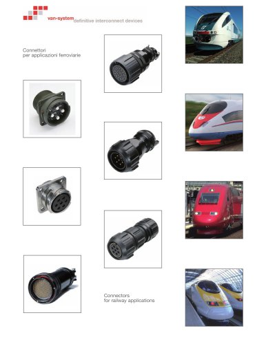
van-systemdefjmtjveinterconnect devices Connettori per applicazioni ferroviarie Connectors for railway applications
Open the catalog to page 1
La soluzione decisiva per tutti i problemi di connessione Definitive interconnect devices La connessione elettrica è uno dei componenti più importanti e insieme critici nella progettazione e nella realizzazione in campo ferroviario, sia che si tratti di apparecchiature utilizzate su mezzi rotabili sia di installazioni per scambio e segnalamento. In railway applications, electrical connection plays a vital role in the process of designing and manufacturing of equipments used for rail transport and signal. Fondamentale è quindi l’utilizzo di connettori elettrici che, oltre ad avere caratteristiche...
Open the catalog to page 3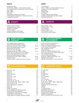
Serie CVBS - CVBSG - GVJ Connettori circolari con accoppiamento a baionetta per utilizzo ferroviario 7 Caratteristiche elettriche dei contatti 9 Caratteristiche di isolamento e di tensione del lavoro 9 CVBS - CVBSG - GVJ Series Bayonet circular connectors for railway applications 7 Contacts electrical characteristics 9 Insulating characteristics and rated voltage 9 Contatti maschi a pinzare 12 Contatti femmina a pinzare 13 Contatti in lega per termocoppie 16 Contatti a pinzare per termocoppie 16 Male contacts - crimp 12 Female contacts - crimp 13 Crimp thermocouple...
Open the catalog to page 4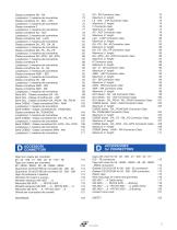
Lunghezza L1 massima del connettore 73 Lunghezza L1 massima del connettore 75 Lunghezza L1 massima del connettore 77 Lunghezza L1 massima del connettore 79 Classe connettore LAC - LACF 80 Lunghezza L1 massima del connettore 81 Classe connettore DA...PG - DA...M 82 Lunghezza L1 massima del connettore 83 Classe connettore DA...FS - RA...FS 84 Lunghezza L1 massima del connettore 85 Classe connettore DA...MTG - RA...MTG 86 Lunghezza L1 massima del connettore 87 Lunghezza L1 massima del connettore 89 Lunghezza L1 massima del connettore 91 Lunghezza L1 massima...
Open the catalog to page 5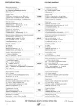
SPIEGAZIONE SIGLA Materiale isolante -: mescola cloroprenica RF: mescola resistente alla fiamma Materiali: p. 17 Codice serie CVBS: con protezione rampe di innesto CVBSG: con ricopertura isolante esterna GVJ: sovradimensionato per impiego gravoso Insulating material -: Chloroprene rubber RF: Flame resistant rubber Materials: p. 17 Series code CVBS: with protected mating ramps CVBSG: with external insulated coating GVJ: oversized for heavy use Tipo di guscio Materiali e trattamenti: p. 54 Caratteristiche e dimensioni: p. 54-65 Tabella compatibilità: p. 66 Shell type Materials and finish: p. 54...
Open the catalog to page 6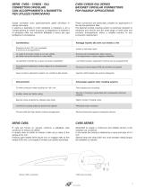
SERIE CVBS - CVBSG - GVJ CONNETTORI CIRCOLARI CON ACCOPPIAMENTO A BAIONETTA PER UTILIZZO FERROVIARIO Questi connettori sono particolarmente adatti all’utilizzo in campo ferroviario. Il sistema a baionetta e molto resistente a vibrazioni e urti e l’ampia gamma di misure di guscio, di disposizioni di isolante e di accessori offre una soluzione affidabile e sicura per ogni problema di connessione. These connectors are particularly suitable for applications in the rail transportation field. The bayonet locking coupling system is extremely resistant to vibrations and shocks and the wide range of shell...
Open the catalog to page 7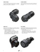
SERIE CVBSG CVBSG SERIES Ha le stesse caratteristiche della serie CVBS ma il connettore volante è fornito ricoperto in gomma per una completa protezione anti infortunistica e da ripetuti urti. Similar to CVBS series but the inline connector is supplied with rubber coated shells for enhanced protection against accidents and shocks. Questa serie è stata progettata per le connessioni volanti fra carrozze o parti di treni. Possiede le stesse funzionalità della serie CVBS con in più caratteristiche quali: • gusci surdimensionati • sistema di polarizzazione a 5 chiavette • ghiera di accoppiamento del...
Open the catalog to page 8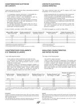
CONTACTS ELECTRICAL CHARACTERISTICS CARATTERISTICHE ELETTRICHE DEI CONTATTI I valori sotto riportati sono validi per utilizzo a temperatura ambiente di 20°C. Si ricorda comunque che: • a temperature crescenti diminuisce la conducibilita fra i contatti e quindi il valore della corrente applicabile • alla corrente di lavoro e alla temperatura di 20°C la temperatura della connessione sale comunque • per quanto sopra, deve essere attentamente considerata la corrente applicabile a una data temperatura e a una determinata misura di contatto • il materiale dell’isolante deve essere scelto non solo in funzione...
Open the catalog to page 9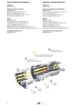
CARATTERISTICHE GENERALI CONTACTS Section A p. 11 INSULATING INSERTS AND GROMMETS Section B p. 17 Inserts and grommets arrangements from p. 18 List by shell size from p. 41 List by contacts total quantity from p. 46 Alternate insert position from p. 50 SHELLS Section C p. 54 Connector shells from p. 54 Connector shells compatibility see table p. 66 Shells mounting data from p. 67 Shielding characteristics from p. 70 Table for rear accessories by class from p. 71 Connectors classes and rear accessories from p. 72 ACCESSORIES FOR CONNECTORS Section D p. 112 CONTATTI Sezione A p. 11 INSERTI ISOLANTI...
Open the catalog to page 10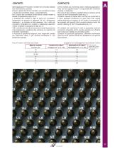
CONTATTI Nelle applicazioni ferroviarie i contatti sono di solito utilizzati con terminazione a pinzare. Possono essere forniti non montati in una confezione inclusa in quella del connettore stesso o separatamente. Per il codice del connettore fornito senza contatti vedere la tabella di spiegazione sigla a p. 6. Il materiale dei contatti e lega di rame con successivo trattamento di doratura di spessore 0.5 mic. (produzione standard) o, su richiesta, di altro spessore. Per i codici dei connettori richiedibili con contatti a trattamento specifico vedere la tabella di spiegazione sigla a p. 6. Tutti...
Open the catalog to page 11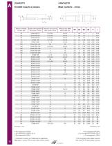
(*) Si riferisce a contatti con trattamento di argentatura Aggiungere il codice CD5 nel caso della versione dorata n P/N concerning silver plated contacts Add code CD5 for gold plated contacts
Open the catalog to page 12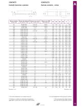
Misura contatto Contact Size
Open the catalog to page 13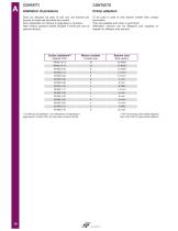
CONTATTI Adattatori di pinzatura Sono da utilizzare nel caso di cavi con una sezione piu piccola di quella del terminale dei contatti. Sono disponibili con finitura di argentatura o doratura. Altre versioni possono essere studiate e fornite per cavi di sezione diversa. CONTACTS Crimp adapters To be used in case of wire section smaller than contact termination. They are available with silver or gold finish. Alternative versions can be designed and supplied on request for different wire sections. O Si riferisce ad adattatori con trattamento di argentatura Aggiungere il codice CD5 nel caso della...
Open the catalog to page 14All Ten47 catalogs and technical brochures
 VanSystem
129 Pages
 Showline 19 Pin Connectors
6 Pages
 Powerline QC
23 Pages


- Data connector
- Electrical power supply connector
- Metal connector
- Screw-in connector
- Industrial connector
- IP67 connector
- Male connector
- Cable connector
- Copper connector
- Screw connector
- Multipole connector
- IEC connector
- Coaxial connector
- Power connector
- Locking connector
- IP68 connector
- M12 electrical connector
- Miniature connector