Powerline Single Power Connectors
1 /18Pages

Powerline Single Power Connectors
1 /18Pages
Catalog excerpts

Ten 47 Limited Unit 2B Frances Industrial Park Kirkcaldy, Scotland, UK KY1 2XZ Tel: +44 (0)1592 655725
Open the catalog to page 1
Powerline Connectors INTRODUCTION TYPICAL APPLICATIONS • Power Distribution • Utilities • Electric Vehicles • Railway Equipment • Military Field Power • Mobile Generators • Loadbanks • Back-up Power Systems BACKGROUND Keyed “L” slot single pole connectors have become widely adopted in a diverse range of applications and industries. One of the main features of early designs was the mechanically keying of the connectors to prevent possible connection errors. I.e. A Phase Line cannot be connected into Earth Line etc. It was evident that several enhancements to existing designs were possible to further...
Open the catalog to page 2
CLIP CONTACT RETENTION SYSTEM • Some versions of this connector format have relie d upon the Electrical Contact being retained within the Insulator by means of a Plastic dowel/cotter pin. • These pins are forced through a mating hole in th e Insulator and contact and any re-use of the same pin may adversely affect the IP sealing of the connectors. • Ten 47 “Powerline” contacts are retained by mean s of a spring clip design that can retain the equivalent weight of 100metres of 240mm² cable. • The contacts are inserted from the rear and “snap ” into position within the Insulator with no requirement...
Open the catalog to page 3
CLIP CONTACT RETENTION SYSTEM • Contacts for 185mm2 to 300mm2 cable can be removed with a simple tool as shown below . Position the contact keyway and insert into the rear of Insulator. Push the cable/contact until the clips “snap” into position. You will feel and hear the locking during this operation. To remove, place the removal tool around the cable and position into the rear of the Insulator. Push the contact from the front and it will release from the Insulator.
Open the catalog to page 4
+ Ten 47 Powerline Connectors PART NUMBER CONFIGURATION CPF CONNECTOR STYLE Cable Connector Cable Plug Panel Socket Panel Inlet INSULATOR COLOUR Green Blue Brown Black Grey Red Yellow White KEY POSITION Earth Neutral Line 1 Line 2 Line 3 CONTACT TERMINATION M12 Post for up to 400 Amps M12 Post for up to 750 Amps Set Screw for up to 120 mm² Crimp Contacts up to 300mm² MODIFICATION CODES Consult Factory Earth Green Green Green Green Neutral Blue Black White Black Line 1 Brown Red Black Red Line 2 Black Yellow Red White Line 3 Grey Blue Blue Blue
Open the catalog to page 5
+ Ten 47 Powerline Connectors CABLE CONNECTOR (line Source) Cable Connectors are typically used as the Live or Supply side of the circuit and utilise a Solid Insulated contact tip to provide IP2X Finger Protection when unmated. “CCF” Connectors incorporate a slot that engages with the Locking Pin on both the mating Panel Inlet and Cable Plug connectors. CABLE PLUG (line Drain) “CPF” Connectors utilise a spring-mounted contact with a Double Insulated Sleeve that provides IP2X Finger Protection when unmated. The “CCF” contact depresses the spring and sleeves to obtain Electrical connection. When...
Open the catalog to page 6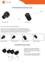
+ Ten 47 Enviromental locking Caps Environmental caps offer increased protection. Enviromental caps are manufactured in high impact Black Acetal with retention line of 1.8mm thick nylon thread crimped with tinplated copper ferrules. In addition to the features of the standard dust cap, they offer IP67 rated sealing and made to fit into keyway to turn and hold in place. Standard Dust Caps CAP-CCF Plastic Push / Pull caps are fitted with available with retention line of 1.8mm thick nylon thread crimped with tinplated copper ferrules. CAP-PSF CAP-PIF ideal for indoor or waterproofed cabinets to...
Open the catalog to page 7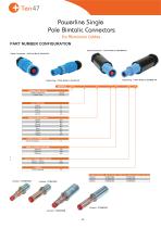
[+ Ten 47 Powerline Single Pole Bimtalic Connectors For Aluminium Cables PART NUMBER CONFIGURATION CONDUCTOR SIZE
Open the catalog to page 8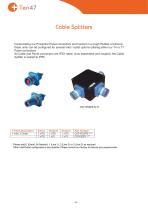
Cable Splitters Incorporating our Powerline Panel connectors and housed in a tough Rubber enclosure, these units can be configured for several inlet / outlet options utilising either our T4 or T7 Panel connectors. All Cable and Panel connectors are IP2X rated, once assembled and coupled, the Cable Splitter is sealed to IP65. T-Piece Description Please add E (Earth), N (Neutral), 1 (Line 1), 2 (Line 2) or 3 (Line 3) as required. Other Inlet/Outlet configurations are possible. P lease consult our factory to discuss any requirements.
Open the catalog to page 9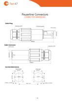
+ Ten 47 Powerline Connectors CONNECTOR DIMENSIONS Cable Plug Cable gland M40 Touch proof Cable Connector Touch proof Cut Out Dimensions Panel Socket Panel Inlet
Open the catalog to page 10
+ Ten 47 Powerline Connectors CONNECTOR DIMENSIONS Touch proof Panel Inlet Touch proof
Open the catalog to page 11
Powerline ConnectorsDEFINITIONS/TERMINOLOGY RATED CURRENT The current rating of the connector is determined by the conductor size and type utilised. Values are taken from IEE wiring regulations BS7671 Table 4F1A Reference method 12 (cables in Free Air). The quoted values relate to non-armoured Single core, copper stranded cable with Rubber insulation and an operating temperature of 85°C. The de-rated values for ambient temperature are taken from Table 4H2A. RATED VOLTAGE The determined voltage of a connector from which the related operating characteristics are defined. CONTACT RESISTANCE The...
Open the catalog to page 12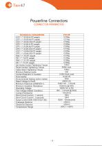
CONNECTOR PARAMETERS
Open the catalog to page 13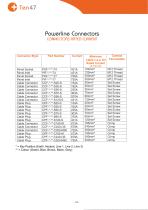
= Key Position (Earth, Neutral, Line 1, Line 2, Line 3) = Colour (Green, Blue, Brown, Black, Grey)
Open the catalog to page 14
REFERENCE DATA FOR CABLE SELECTION The Current Rating of the connector is determined by the conductor size and type utilised. For this publication, values are taken from IEE wiring regulations BS7671 Table 4F1A Reference Method 12 (Free Air). The quoted values relate to non-armoured Single Core, Copper stranded cables with Rubber Insulation and an operating temperature of 85ºC. Derating Data for 85° Rubber Insulated Cables C Current Amps Powerline contacts are suitable for termination onto Aluminium conductors for short term applications.. However, we recommend that bi-metallic contacts or cable...
Open the catalog to page 15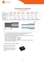
Powerline ConnectorsTOOLS AND DATA Cable Size • It is recommended to apply multiple crimp compress ions in accordance with the above table to obtain optimum mechanical and electrical performance. • The correct sequence of compressions is as shown a bove. • When correctly terminated, the Electrical and Mech anical performance of the Crimp will be in accordance with IEC61238-1. • 185mm2 Crimp: Tensile Strength = 11,100N min. • 240mm2 Crimp: Tensile Strength = 14,400N min. * 300mm2 Crimp: Tensile Strength = 18,000N min. ’ Due to the numerous cable types available, it is r ecommended to contact Ten...
Open the catalog to page 16All Ten47 catalogs and technical brochures
 VanSystem
129 Pages
 Showline 19 Pin Connectors
6 Pages
 Powerline QC
23 Pages


- Data connector
- Electrical power supply connector
- Metal connector
- Round connector
- Screw-in connector
- Industrial connector
- Circular connector
- IP67 connector
- Male connector
- Copper connector
- Screw connector
- Multipole connector
- IEC connector
- Coaxial connector
- Power connector
- IP68 connector
- Locking connector
- M12 electrical connector