

S6 DC

S6 DC
Overview
This document provides detailed technical specifications, dimensions, electrical ratings, mechanical features, and accessory options for a series of DC switch-disconnectors designed for photovoltaic (PV) and other DC applications. The devices comply with IEC 60947-1 and IEC 60947-3 standards and UL98B certification, suitable for voltages of 500 Vdc, 750 Vdc, and 1000 Vdc.
1. Product Specifications
1.1 Rated Thermal Current (Ith)
- Available ratings: 125 A, 160 A, 200 A, 250 A, 315 A, 400 A, 500 A, 630 A
- Thermal current ratings are consistent across ambient temperatures of 40ºC, 50ºC, and 60ºC
1.2 Rated Operational Current (Ie)
- Operational current ratings correspond to the voltage codes (500 Vdc, 750 Vdc, 1000 Vdc) and match the thermal current ratings
1.3 Rated Insulation and Impulse Withstand Voltage
- Insulation voltage (Ui): 1500 Vdc for all models
- Impulse withstand voltage (Uimp): 12 kV for all models
1.4 Short-Circuit Behavior
- Rated short-circuit making capacity (Icm): 10 kA peak for all ratings
- Rated short-time withstand current (Icw) for 1 second: 10 kA rms
- Short-circuit rating maintained without limiting protective device for 50 to 100 ms
2. Mechanical Features
- Number of mechanical operations: 8000 cycles for ratings up to 315 A, 5000 cycles for 400 A and above
- Maximum weight varies by code; consult manufacturer
- Torque specifications for lug bolts and terminal connections provided (e.g., 375 lb.inch / 42 Nxm for 400 A)
3. Dimensions and Wiring
- Detailed dimensions provided for all sizes, including length (L), width (P), and mounting hole diameters
- Wiring capacity ranges from minimum AWG/MCM sizes (e.g., 3/0 AWG or 85 mm²) to maximum (e.g., 400 kcmil or 240 mm²)
- Terminal lug and bolt sizes specified (e.g., M12 bolts, 11/16-16 UNF)
- Phase barriers and terminal shrouds recommended to maintain required clearances
4. Accessories
- Safety key lock devices: simple and double versions available for external handle locking
- Phase barriers: available in units of 1, 2, or 3 to maintain electrical clearance
- Terminal shrouds and spacers for enhanced safety and installation flexibility
- Handles: direct, external without shaft (IP65), and external with shaft (IP65)
- Auxiliary contacts: 1NO+1NC and 2NO+2NC configurations rated for 16 A resistive and 4 A inductive loads at 250 Vac
- Shaft extensions available for longer handle reach
5. Standards and Certifications
- Compliant with IEC 60947-1 and IEC 60947-3 standards
- UL98B certification for PV disconnect switches, suitable for use in photovoltaic systems per NEC Article 690
- Rated for operation in ambient temperatures from -20ºC to +50ºC
6. Installation and Usage Recommendations
- Use of phase barriers is mandatory when terminal lugs are installed to maintain required clearances
- Consult manufacturer for installations involving grounded systems
- Torque values for terminal connections must be respected to ensure safety and performance
- Door drilling templates and external handle installation instructions are available upon request
7. Summary of Key Parameters by Size
| Size | Rated Current (A) | Voltage (Vdc) | Short-Circuit Capacity (kA) | Mechanical Operations (cycles) | Torque (Nxm) |
|---|---|---|---|---|---|
| Size 1 | 125 - 400 | 500 / 750 / 1000 | 10 | 8000 (up to 315 A), 5000 (400 A) | 24 - 30 |
| Size 2 | 500 - 630 | 500 / 750 / 1000 | 10 | 5000 | 24 |
Conclusion
The document comprehensively details the technical and mechanical characteristics of DC switch-disconnectors suitable for photovoltaic and other DC applications. It emphasizes compliance with international standards, safety features, and accessory options to ensure reliable and safe operation. Proper installation practices, including the use of phase barriers and adherence to torque specifications, are critical for optimal performance.
Catalog excerpts
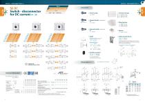
series series Switch - disconnector for DC current 1P - 2P CODE DR-CU11 (1 unit) CODE DR-CU12 (1 unit) CODE DR-CU13 (1 unit) xternal handle included shaft * E xternal handle without shaft E external handle, lock the handle by means of a key in For position “OFF” (under request, in “ON”), the key can only be removed with the handle locked Shaft extensions Type 1 Rated short-circuit making capacity *(2) Short - circuit behaviour Rated impulse Uimp withstand voltage Rated operational Ie current *(1) Code 500 Vdc Code 750 Vdc Code 1000 Vdc Door drilling for external handle Rated short-time withstand Icw current (1sec) Maximum weight Consult according to code *(1) Other voltages and / or utilization categories. Please consult *(2) Without limiting protective device (short-circuit maintained 50... 100 ms.) Mechanical features Number of mechanical operations Cycles 8000 8000 8000 8000 8000 5000 (according to the standards, for other values please consult) Rated insulation voltage (DC) 125 160 200 250 315 400 Rated thermal current in ambient at Technical information Ie = 16 A (resistive loads) 4 A (inductive loads) at 250 Vac. 2X 2Y CONSULT FOR GROUNDED INSTALLATIONS Door drilling for handle and key lock device Simple Double Standard shaft included * afety key lock device S
Open the catalog to page 1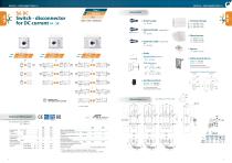
Switch - disconnector for DC current 1P - 2P CODE DR-CU21 (1 unit) CODE DR-CU22 (1 unit) CODE DR-CU23 (1 unit) xternal handle included shaft * E hase barriers P CODE xternal handle without shaft E Standard shaft included *(e1) Door drilling for handle and key lock device Simple Double ,5 (Using phase barriers DR-SF_ _ to maintain the required clearance) Shaft extensions afety key lock device S Ie = 16 A (resistive loads) 4 A (inductive loads) at 250 Vac. tests: consult Rated short-circuit making capacity *(2) Rated insulation voltage (DC) Rated impulse Uimp withstand voltage Number of mechanical...
Open the catalog to page 2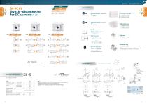
Switch - disconnector for DC current 1P - 2P xternal handle included shaft * E CODE DR-CU11 (1 unit) CODE DR-CU12 (1 unit) CODE DR-CU13 (1 unit) xternal handle without shaft E Standard shaft included *(e1) L (mm) * (1) ith Terminal lug use phase barriers DR-SF_ _ to maintain W the required clearance. Mandatory in these models Ie = 16 A (resistive loads) 4 A (inductive loads) at 250 Vac. Shaft extensions Technical information Door drilling for external handle CONSULT FOR GROUNDED INSTALLATIONS 250 Rated thermal current Ith Rated operational current 250 A Conforms to UL98B. Minus 20 to +50ºC....
Open the catalog to page 3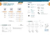
Switch - disconnector for DC current 1P - 2P series series xternal handle included shaft * E CODE DR-CU21 (1 unit) CODE DR-CU22 (1 unit) CODE DR-CU23 (1 unit) xternal handle without shaft E Standard shaft included *(e1) L (mm) Ie = 16 A (resistive loads) 4 A (inductive loads) at 250 Vac. * (1) ith Terminal lug use phase barriers DR-SF_ _ to maintain W the required clearance. Mandatory in these models 400 Rated thermal current Ith Rated operational current Rated short-circuit current Maximum weight 400 A Conforms to UL98B. Minus 20 to +50ºC. PV disconnects switch. Location Category B 1000...
Open the catalog to page 4All Telergon catalogs and technical brochures
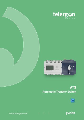 ATS
ATS8 Pages
 S5M DC
3 Pages
 S6R DC
2 Pages
 S6N DC
2 Pages
 S5 DC
S5 DC5 Pages
 CIF22
CIF222 Pages
 M21 M21 series
3 Pages
 series CTR
7 Pages
 CCF CCP
3 Pages
 S5F
S5F6 Pages
 CEC series
2 Pages
 CIS25 - A - C - D - F
6 Pages
 S6N AC
2 Pages
 S5M AC
4 Pages
 S6 AC
S6 AC2 Pages
 S5 AC
S5 AC9 Pages
 ZBK
ZBK4 Pages
 CITA
CITA4 Pages
 CITP CTFR
3 Pages
 TP T TB TF
8 Pages
 Enclosed solutions
3 Pages
 Cam switches
17 Pages
 Enclosed cam switches
18 Pages


- Single-pole switch
- Multipole switch
- Multipole disconnect switch
- Metal switch
- Plastic switch
- Bipolar switch
- 3-pole switch disconnector
- IP65 switch
- Transfer switch
- AC electric switch
- 4-pole switch disconnector
- Low-voltage main switch
- AC disconnector
- Door switch
- IEC switch
- Automatic transfer switch
- IEC disconnector
- Rotary main switch
- Automatic disconnector