

S6 AC

S6 AC
Overview
This document provides detailed technical specifications, accessories, and installation guidelines for the S6 series of switch-disconnectors compliant with IEC 60947-3 standards. The series includes 2-pole (2P), 3-pole (3P), and 3-pole plus neutral (3P+N) configurations, with current ratings ranging from 250A up to 800A.
Technical Specifications
- Rated Thermal Current (Ith): Available for 40ºC, 50ºC, and 60ºC ambient temperatures, with values from 250A to 800A depending on model size.
- Rated Insulation Voltage (Ui): 1000 V across all models.
- Rated Impulse Withstand Voltage (Uimp): 12 kV for all variants.
- Rated Operational Current (Ie): Triphasic currents at 400V (AC23A) and 690V (AC21A) with values matching the rated thermal current.
- Short-Circuit Performance: Rated short-circuit making capacity (Icm) peaks at 20 kA for sizes up to 500A and 26 kA for 630A and 800A models. Rated short-time withstand current (Icw) is 12 kA for smaller sizes and 16 kA for larger sizes (1 second duration).
- Mechanical Endurance: 8000 cycles for sizes up to 500A and 5000 cycles for 630A and 800A models.
- Weight: Varies by configuration and size, e.g., 1.65 to 2.76 kg for smaller sizes and up to 5.7 kg for larger models.
Dimensions and Mounting
Dimensions vary by size and pole configuration, with detailed measurements provided for height, length, and mounting hole diameters. Mounting positions must comply with installation instructions; notably, installation at 270 degrees orientation is prohibited.
Accessories and Options
- Safety Key Lock Devices: Available in simple and double key codes (e.g., DS-CA11, DS-CE11 for smaller sizes; DS-CB21, DS-CF21 for larger sizes). Keys lock the handle in OFF position (optional ON position) and can only be removed when locked.
- Phase Barriers: Modular units (DR-SF11 to DR-SF13 for smaller sizes, DR-SF21 to DR-SF23 for larger sizes) to maintain required clearances.
- Terminal Shrouds: Protective covers (DR-CU11 to DR-CU13 and DR-CU21 to DR-CU23) for terminals.
- Spacers: Sets of four units (DR-EL11 and DR-EL21) for installation spacing.
- Handles: Direct handles (DS-SI11, DS-LI21), external handles with or without shafts (IP65 rated), and emergency external handles with shafts.
- Auxiliary Contacts: Options include 1NO+1NC and 2NO+2NC contacts rated at 16 A resistive and 4 A inductive loads at 250 Vac.
- Shaft Extensions: Two types available with varying lengths and codes for extended mounting flexibility.
Electrical and Mechanical Notes
- Short-circuit ratings are specified without limiting protective devices, with short-circuit durations maintained between 50 to 100 ms.
- Phase barriers are recommended to maintain required electrical clearances.
- 4-pole switch-disconnectors are available upon request.
- Torque specifications for terminal connections are provided (e.g., M12 screws tightened to 24 Nm).
Installation Recommendations
Installation must follow the provided drilling templates for door mounting and handle/key lock devices. The orientation of the switch-disconnector is critical; installation at 270 degrees is not allowed. Consult installation instructions for acceptable mounting positions.
Summary of Key Parameters by Size
| Parameter | 250-315A | 400A | 500A | 630A | 800A |
|---|---|---|---|---|---|
| Rated Thermal Current (Ith) @ 40ºC | 250-315 A | 400 A | 500 A | 630 A | 800 A |
| Rated Short-Circuit Making Capacity (Icm) | 20 kA | 20 kA | 20 kA | 26 kA | 26 kA |
| Rated Short-Time Withstand Current (Icw) | 12 kA | 12 kA | 12 kA | 16 kA | 16 kA |
| Mechanical Operations | 8000 cycles | 8000 cycles | 8000 cycles | 5000 cycles | 5000 cycles |
| Weight (3P+N) | ~2.7 kg | ~2.7 kg | ~2.76 kg | 5.7 kg | 5.7 kg |
| Rated Operational Current (Ie) @ 400V AC23A | 250-315 A | 400 A | 500 A | 630 A | 800 A |
Conclusion
The S6 series switch-disconnectors offer robust electrical and mechanical performance suitable for industrial applications requiring reliable switching and isolation. The availability of multiple accessories enhances safety and installation flexibility. Compliance with IEC 60947-3 ensures standardized quality and performance. Proper installation and adherence to mounting orientation are critical for optimal operation.
Catalog excerpts

Direct handle CODE Switch - disconnector base mounting 2P - 3P - 3P+N Terminal shrouds CODE CODE External handle Phase barriers External handle without shaft Safety key lock device Standard shaft included *(e1) L (mm) Shaft extensions Short-circuit behaviour Rated short-circuit making capacity *(2) Icm kA (peak) Rated short-time withstand current (1sec) Rated impulse withstand voltage Rated breaking capacity Rated making capacity Number of mechanical operations (according Cycles to the standards, for other values please consult) CODE CODE Door drilling for external handle * Other voltages and / or utilization categories. Please consult *(2) Without limiting protective device (short-circuit maintained 50... 100 ms.) *(3) 3P/3P+N 4P Also available 4P switch-disconnectors under request, please consult Warning: For the acceptable mounting positions, please consult the installation instructions. Do not install at 270 degrees orientation. Mechanical features Mounting positions Ie = 16 A (resistive loads) 4 A (inductive loads) at 250 Vac. Auxiliary contacts Rated insulation voltage AC Rated operational current*(1) Technical information Rated thermal current in ambient at Door drilling for handle and key lock device Simple Double For external handle, lock the handle by means of a key in position “OFF” (under request, in “ON”), the key can only be removed with the handle locked Simple CODE DS-CA11 Double CODE DS-CE11 Emergency external handle *(t1) Using phase barriers DR-SF_ _ to maint
Open the catalog to page 1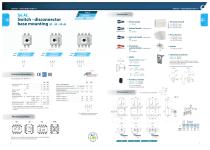
Direct handle CODE Switch - disconnector base mounting 2P - 3P - 3P+N Terminal shrouds CODE CODE External handle Phase barriers External handle without shaft Emergency external handle Safety key lock device Simple CODE DS-CB21 Double CODE DS-CF21 Standard shaft included *(e1) L (mm) For external handle, lock the handle by means of a key in position “OFF” (under request, in “ON”), the key can only be removed with the handle locked Shaft extensions Door drilling for handle and key lock device Simple Double Technical information Ie = 16 A (resistive loads) 4 A (inductive loads) at 250 Vac. Rated...
Open the catalog to page 2All Telergon catalogs and technical brochures
 ATS
ATS8 Pages
 S5M DC
3 Pages
 S6R DC
2 Pages
 S6N DC
2 Pages
 S6 DC
S6 DC4 Pages
 S5 DC
S5 DC5 Pages
 CIF22
CIF222 Pages
 M21 M21 series
3 Pages
 series CTR
7 Pages
 CCF CCP
3 Pages
 S5F
S5F6 Pages
 CEC series
2 Pages
 CIS25 - A - C - D - F
6 Pages
 S6N AC
2 Pages
 S5M AC
4 Pages
 S5 AC
S5 AC9 Pages
 ZBK
ZBK4 Pages
 CITA
CITA4 Pages
 CITP CTFR
3 Pages
 TP T TB TF
8 Pages
 Enclosed solutions
3 Pages
 Cam switches
17 Pages
 Enclosed cam switches
18 Pages


- Single-pole switch
- Isolator switch
- Multipole switch
- Multipole disconnect switch
- Metal switch
- Plastic switch
- Bipolar switch
- 3-pole switch disconnector
- IP65 switch
- Transfer switch
- AC electric switch
- 4-pole switch disconnector
- Low-voltage main switch
- AC disconnector
- Door switch
- IEC switch
- Automatic transfer switch
- IEC disconnector
- Rotary main switch
- Automatic disconnector