- Products
- Catalogs
- News & Trends
- Exhibitions
Cam switches
1 /17Pages

Cam switches
1 /17Pages
Catalog excerpts
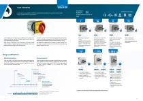
Cam switches available in different construction models over a wide current range with a large variety of accessories. IEC 60947-3 UL508 - CAN/CSA C22.2 Nº 14 RoHS series Cam switches are manufactured in different series under strict quality controls to provide a reliable product that meets the most demanding requirements. In sizes 0 - 1 and 2, the terminals are equipped with captive clamp screws to facilitate installation work, and all the connections themselves are covered to provide an IP20 protection rating. They consist of chambers, each containing up to two double break contacts of positive...
Open the catalog to page 2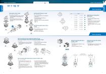
FIXING TYPES OR MODELS Door mounting Door mounting for Ø 22 mm available for sizes 0 and 1. Door mounting for metal nut Ø 22 mm available for sizes 0 and 1. Multidrill plates for different fixing distances. Fixing with two screws for mounting without base nor indicating plate. Central fixing with metal nut Ø 22 Z type For T - TF series (also Ø 30 mm under request). Multi-distance fixing plates with screws For T - TB - TF series Maximum number of chambers supported Size 0 = 6 Size 1 = 4 For arrow handle with indicator or padlockable handle. Door mounting with arrow handle, indicating...
Open the catalog to page 3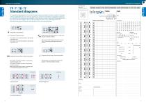
Inscription plate Name plate ORDER SHEET FOR NON-STANDARD CAM SWITCHES 10 TO 315 AMP. Standard diagrams Series Contact closed Closed contact without interruption Late break contact Early-make contact Return from 30º For many switching operations that can be resolved using cam switches, we have a number of standard schemes applicable to the most common applications in electrical installations, equipment, machinery, etc. If you do not find what you are looking for in this selection, or have a special switching requirement, you can use the blank diagrams form on the next page and send it to our...
Open the catalog to page 4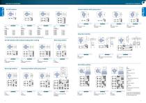
On-Off switches Control switches with spring return 2 5 poles 6 poles 7 poles 8 poles 9 poles 10 poles 11 poles 12 poles 13 poles 14 poles 15 poles 16 poles 17 poles 18 poles 19 poles 20 poles 21 poles 22 poles 23 poles 24 poles 201 Start switch 1 pole 1 chamber 202 Stop switch 1 pole 1 chamber 203 Start switch 2 poles 1 chamber 204 Stop switch 2 poles 1 chamber Stop-Start switches To view these wiring diagrams please visit our download area on www.telergon.com On-Off switches with contacts leading when making Reversing switches 020 3 poles 1 preclosed pole 2 chambers 021 4 poles 1 preclosed...
Open the catalog to page 5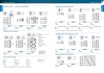
Split phase starting switches Changeover switches with center “Off” 0 Start delta switches 315 Start return to 1 2 chambers 316 Reversing type of T315 1 - ARR - 0 - ARR - 2 3 chambers 317 Start single phase 2 voltages 3 chambers 332 Reversing type of T330 7 chambers To view these wiring diagrams please visit our download area on www.telergon.com 342 0 - A - B en λ or Δ 0-1-2 3 chambers 343 Reversing del 342 2-1-0-1-2 5 chambers 344 ΔB - λB- 0 - λA - ΔA 1-λ-0-λ-2 8 chambers 350 0 - λA - ΔB - λ λB 0-1-2-3 6 chambers To view these wiring diagrams please visit our download area on www.telergon.com...
Open the catalog to page 6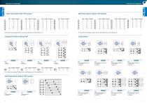
Multi-step switches with “Off” position To view these wiring diagrams please visit our download area on www.telergon.com 601 1 pole switching sequence 0 - A - (A+B) 1 chamber 602 2 poles switching sequence 0 - A - (A+B) 2 chambers 603 1 pole switching sequence 0 - A - B - (A+B) 1 chamber 604 2 poles switching sequence 0 - A - B - (A+B) 2 chambers To view these wiring diagrams please visit our download area on www.telergon.com Changeover switches without “Off” 1 To view these wiring diagrams please visit our download area on www.telergon.com Multi-step switches without “Off” position 605 1 pole...
Open the catalog to page 7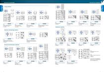
Gang switches 609 3 poles switching sequence 0 - A - (A+B) - (A+B+C) 5 chambers 610 Switching sequence λ 0 - A - (A+B) - (A+B+C) 2 chambers 611 Switching sequence Δ 0 - A - (A+B) - (A+B+C) 2 chambers 612 Switching sequence 0 - A + B series A - B - (A + B) paralell 2 chambers 630 Switching sequence 0 - A - (A+B) - (A+B+C) 2 chambers 632 Switching sequence 0 - A - (A+B) - (A+B+C) - (A+B+C+D) (A+B+C+D+E) 3 chambers Voltmeter switches Kitchen and heating switches 1 613 3 positions switching sequence 0-A+B paralell; A or B-A+B series -0 3 chambers 614 3 positions switching sequence 0-A+B series;...
Open the catalog to page 8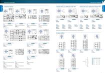
Switches for B.C.D. codification with “Off” 720* 3 phases, 3 current transformers, 1 pole 4 chambers 721 3 phases, 2 current transformers, 1 pole 2 chambers Switches for B.C.D. codification without “Off” 724 3 phases, 2 current transformers, 1 pole 2 chambers 725 4 lines, 4 current transformers, 1 pole 4 chambers To view these wiring diagrams please visit our download area on www.telergon.com L3 By-pass switches 727 3 lines, 3 current transformers, 2 poles 6 chambers 730 2 current transformers, 1 pole 2 chambers 731* 3 current transformers, 1 pole 4 chambers * New diagram 733 732 3 phases, 3...
Open the catalog to page 9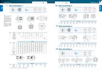
Door mounting drilling *(ch) Central quick fixing ø22 - maximun number of chambers supported. without plate Door mounting drilling Note: The cam switches allow a construction up to 12 chambers (24 contacts). It’s necessary to distribute in several columns (maximum three of 12 chambers each) when the number of contacts is higher than 24, so we use the tandem drives D200 or D201. Depending on the number of contacts to be switched simultaneously, it’s possible to supply up to 14 chambers switches in size 0. Door mounting drilling Door mounting drilling Door mounting
Open the catalog to page 10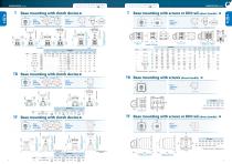
*(2) Modular enclosure 3 chambers max TF Base mounting with screws or DIN rail (direct handle) 50 Panel mounting drilling Panel mounting drilling 12 chambers max. by screws 6 chambers max. DIN rail 12 chambers max. by screws 6 chambers max. DIN rail 12 chambers max. by screws 6 chambers max. DIN rail Frontal panel mecanization with 2 or 4 screws Panel mounting drilling TB Base mounting with screws (direct handle) TF Base mounting with clutch device H9-H10 *(1) Modular enclosure 3 chambers max Panel mounting drilling Door drilling for handle Frontal panel mecanization with 2 or 4 screws Door...
Open the catalog to page 11All Telergon catalogs and technical brochures
 ATS
ATS8 Pages
 S5M DC
3 Pages
 S6R DC
2 Pages
 S6N DC
2 Pages
 S6 DC
S6 DC4 Pages
 S5 DC
S5 DC5 Pages
 CIF22
CIF222 Pages
 M21 M21 series
3 Pages
 series CTR
7 Pages
 CCF CCP
3 Pages
 S5F
S5F6 Pages
 CEC series
2 Pages
 CIS25 - A - C - D - F
6 Pages
 S6N AC
2 Pages
 S5M AC
4 Pages
 S6 AC
S6 AC2 Pages
 S5 AC
S5 AC9 Pages
 ZBK
ZBK4 Pages
 CITA
CITA4 Pages
 CITP CTFR
3 Pages
 TP T TB TF
8 Pages
 Enclosed solutions
3 Pages
 Enclosed cam switches
18 Pages


- Single-pole switch
- Isolator switch
- Multipole switch
- Multipole disconnect switch
- Metal switch
- Plastic switch
- Bipolar switch
- 3-pole switch disconnector
- IP65 switch
- Transfer switch
- AC electric switch
- Low-voltage main switch
- 4-pole switch disconnector
- AC disconnector
- Automatic transfer switch
- IEC switch
- Door switch
- IEC disconnector
- Rotary main switch