- Company
- Products
- Catalogs
- News & Trends
- Exhibitions
732
1 /6Pages

732
1 /6Pages
Catalog excerpts
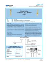
TELEDYNE RELAYS Everywhereyoulook" Series 732 DPDT Non-Latching Commercial Electromechanical Relay © 2016 TELEDYNE RELAYS (800) 284-7007 • www.teledynerelays.com
Open the catalog to page 1
TELEDYNE RELAYS Everywhereyoulook' Series 732 DPDT Non-Latching Commercial Electromechanical RelaySERIES 732 GENERAL ELECTRICAL SPECIFICATIONS (@25°C) Contact Arrangement DETAILED ELECTRICAL SPECIFICATIONS (@25°C) BASE PART NUMBERS (732, 732D, 732TN) GENERAL NOTES 1. Relay contacts will exhibit no chatter in excess of 10 psec or transfer in excess of 1 ^sec. 2. “Typical” characteristics are based on available data and are best estimates. No on-going verification tests are performed. 3. Unless otherwise specified, parameters are initial values. 4. Relays can be supplied with a spacer pad. See...
Open the catalog to page 2
DPDT Non-Latching Commercial Electromechanical Relay SERIES 732 OUTLINE DIMENSIONS CASE DETAIL .370 (9.40) DIA. MAX. TERMINAL LOCATIONS AND PIN NUMBERING (REF. ONLY) (Viewed from Terminals) (Viewed From Terminals) NOTES: 1. RELAY CONTACTS WILL EXHIBIT NO CHATTER IN EXCESS OF 10 ΜSEC OR TRANSFER IN EXCESS OF 1 ΜSEC. 2. “TYPICAL” CHARACTERISTICS ARE BASED ON AVAILABLE DATA AND ARE BEST ESTIMATES. NO ON-GOING VERIFICATION TESTS ARE PERFORMED. 3. UNLESS OTHERWISE SPECIFIED, PARAMETERS ARE INTIAL VALUES. 4. FOR REFERENCE ONLY. COIL RESISTANCE NOT DIRECTLY MEASURABLE ON 732TN RELAYS. 5. CIRCUIT IS...
Open the catalog to page 3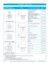
APPENDIX: Spacer Pads Pad designation and bottom view dimensions Notes: 1. Spacer pad material: Polyester film. 2. To specify an “M4” or “M9” spacer pad, refer to the mounting variants portion of the part numbering example in the applicable datasheet. 3. Dimensions are in inches (mm). 4. Unless otherwise specified, tolerance is ± .010” (.25 mm). 5. Add 10 mΩ to the contact resistance shown in the datasheet. 6. Add 0.01 oz. (0.25 g) to the weight of the relay assembly shown in the datasheet. Page 4
Open the catalog to page 4
Pad designation and bottom view dimensionsFor use with the following: Dim. H Max. 1. Spreader pad material: Diallyl Phthalate. 2. To specify an “M”, “M2” or “M3” spreader pad, refer to the mounting variants portion of the part number example in the applicable datasheet. 4. Unless otherwise specified, tolerance is ± .010” (0.25 mm). 5/. Add 25 mQ to the contact resistance shown in the datasheet. 6/. Add .01 oz. (0.25 g) to the weight of the relay assembly shown in the datasheet. 7/. Add 50 mQ to the contact resistance shown in the datasheet. 8/. Add 0.025 oz (0.71 g) to the weight of the relay...
Open the catalog to page 5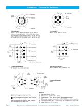
APPENDIX: Ground Pin Positions "Z" Centigrid® Relays: Centigrid® Relays: Indicates ground pin position Indicates glass insulated lead position Indicates ground pin or lead position depending on relay type Page 6 NOTES 1. Terminal views shown 2. Dimensions are in inches (mm) 3. Tolerances: ± .010 (±.25) unless otherwise specified 4. Ground pin positions are within .015 (0.38) dia. of true position 5. Ground pin head dia., 0.035 (0.89) ref: height 0.010 (0.25) ref. 6. Lead dia. 0.017 (0.43) nom.
Open the catalog to page 6All Teledyne Relays catalogs and technical brochures
 Space product selction guide
62 Pages
 Product overview
28 Pages
 722
7223 Pages
 712
7126 Pages
 H-33S
H-33S6 Pages
 Series HR412/ HRS412
10 Pages
 E3P Series
4 Pages
 LS10 Series
2 Pages
 Series EMCRT
4 Pages
 S3P series
2 Pages
 Series SQ
2 Pages
 Miniature Matrix
1 Page
 Matrix Selection Guide
28 Pages


Archived catalogs
 Series HR255/HR257
11 Pages
 Series H-32N
6 Pages
 172
1726 Pages
 122C
122C6 Pages


- Single-pole switch
- Switching relay
- Technology switch
- Multipole switch
- Electromechanical switch
- DC electromechanical relay
- Solid state relay
- Transfer switch
- Printed circuit board electromechanical relay
- Power relay
- DC solid state relay
- AC electromechanical relay
- 12VDC electromechanical relay
- 3-pole electric switch
- Mechanical switch
- Interlock electric switch
- Bistable electromechanical relay
- Compact electromechanical relay
- Power solid state relay