- Company
- Products
- Catalogs
- News & Trends
- Exhibitions
722
1 /3Pages

722
1 /3Pages
Catalog excerpts
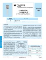
B^TELEDYNE RELAYS A Unit of Teledyne Electronics and Communications COMMERCIAL TO-5 RELAYS DPDT MAGNETIC LATCHING SERIES DESIGNATION DESCRIPTION The magnetic-latching TO-5 relay, originally conceived and developed by Teledyne, has become one of the industry standards for low-level switching from dry circuit to 1 ampere. Designed for high-density PC board mounting, the 722 relay has become one of the most versatile ultraminiature relays available because of its small size and low coil power dissipation. Unique construction features and manufacturing techniques provide excellent resistance to environmental extremes and overall high reliability. • All welded construction. • Unique uni-frame design providing high magnetic efficiency and mechanical rigidity. • High force/mass ratios for resistance to shock and vibration. • Advanced cleaning techniques provide maximum assurance of internal cleanliness. • Precious metal alloy contact material with gold plating assures excellent high current and dry circuit switching capabilities. The Series 722D relay has discrete silicon diodes for coil transient suppression. The Series 722 magnetic-latching relays are ideally suited for applications where coil power dissipation must be minimized. The relays can be operated with a short duration pulse and after the contacts have transferred, no external coil power is required. The magnetic-latching feature of the Series 722 provides a “memory” capability, since the relays will not reset upon removal of coil power. By virtue of its inherently low intercontact capacitance and contact circuit losses, the 722 relay has proven to be an excellent ultraminiature RF switch for frequency ranges well into the UHF spectrum. A typical RF application for the TO-5 relay is in handheld radio transceivers, wherein the combined features of good RF performance, small size, low coil power dissipation and high reliability make it a preferred method of Transmitter-Receive switching (see Figure 1). PRINCIPLE OF OPERATION Energizing Coil B produces a magnetic field opposing the holding flux of the permanent magnet in Circuit B. As this net holding force decreases, the attractive force in the air gap of Circuit A, which also results from the flux of the permanent magnet, becomes great enough to break the armature free of Core B, and snap it into a closed position against Core A. The armature then remains in this position upon removal of power from Coil B, but will snap back into position B upon energizing Coil A. Since operation depends upon cancellation of a magnetic field, it is necessary to apply the correct polarity to the relay coils as indicated on the relay schematic. When latching relays are installed in equipment, the latch and reset coils should not be pulsed simultaneously. Coils should not be pulsed with less than rated coil voltage and the pulse width should be a minimum of three times the specified operate time of the relay. If these conditions are not followed, it is possible for the relay to be in the magnetically neutral position. ENVIRONMENTAL AND PHYSICAL SPECIFICATIONS ©2003 TELEDYNE RELAYS SPECIFICATIONS ARE SUBJECT TO CHANGE WITHOUT NOTICE
Open the catalog to page 1
SERIES 722 GENERAL ELECTRICAL SPECIFICATIONS (@25°C) (Notes 2 & 3) Contact Arrangement Rated Duty Contact Resistance 2 Form C (DPDT) Continuous 0.15 ohm max. before life; 0.25 ohm max. after life at 1A/28Vdc (measured 1/8" from header) Contact Load Ratings (DC) (See Fig. 2 for other DC resistive voltage/current ratings) Resistive: Inductive: Lamp: Low Level: Contact Load Ratings (AC) 250 mA/115Vac, 60 and 400 Hz (Case not grounded) 100 mA/115Vac, 60 and 400 Hz (Case grounded) Contact Life Ratings 10,000,000 cycles (typical) at low level 1,000,000 cycles (typical) at 0.5A/28Vdc resistive 100,000...
Open the catalog to page 2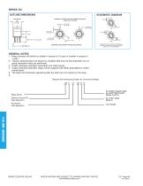
SERIES 722 OUTLINE DIMENSIONS SCHEMATIC DIAGRAM TERMINAL LOCATIONS AND PIN NUMBERS (REF. ONLY) (Viewed from Terminals) DIMENSIONS ARE SHOWN IN INCHES (MILLIMETERS) COIL A 722D SCHEMATICS ARE VIEWED FROM TERMINALS. CONTACTS SHOWN IN POSITION RESULTING WHEN COIL A LAST ENERGIZED. GENERAL NOTES 1. Relay contacts will exhibit no chatter in excess of 10 µsec or transfer in excess of 1 µsec. 2. “Typical” characteristics are based on available data and are best estimates. No ongoing verification tests are performed. 3. Unless otherwise specified, parameters are initial values. 4. Unless otherwise specified,...
Open the catalog to page 3All Teledyne Relays catalogs and technical brochures
 Space product selction guide
62 Pages
 Product overview
28 Pages
 732
7326 Pages
 712
7126 Pages
 H-33S
H-33S6 Pages
 Series HR412/ HRS412
10 Pages
 E3P Series
4 Pages
 LS10 Series
2 Pages
 Series EMCRT
4 Pages
 S3P series
2 Pages
 Series SQ
2 Pages
 Miniature Matrix
1 Page
 Matrix Selection Guide
28 Pages


Archived catalogs
 Series HR255/HR257
11 Pages
 Series H-32N
6 Pages
 172
1726 Pages
 122C
122C6 Pages


- Single-pole switch
- Switching relay
- Technology switch
- Multipole switch
- Electromechanical switch
- Electromechanical relay
- DC electromechanical relay
- Solid state relay
- Transfer switch
- Power relay
- Printed circuit board electromechanical relay
- DC solid state relay
- AC electromechanical relay
- 12VDC electromechanical relay
- Mechanical switch
- Bistable electromechanical relay
- Interlock electric switch
- Compact electromechanical relay
- Power solid state relay
- 3-pole electric switch