- Company
- Products
- Catalogs
- News & Trends
- Exhibitions
712
1 /6Pages

712
1 /6Pages
Catalog excerpts

TELEDYNE RELAYS Everywhereyoulook" Series 712 DPDT Non-Latching Commercial Electromechanical Relay COMMERCIAL TO-5 RELAYS DPDT SERIES RELAY TYPE 712 DPDT basic relay DPDT relay with internal diode for coil transient suppression DPDT relay with internal transistor driver and coil transient suppression diode DESCRIPTION The TO-5 relay, originally conceived and developed by Teledyne, has become one of the industry standards for low-level switching from dry circuit to 1 ampere. Designed for high-density PC board mounting, the Series 712 relays are some of the most versatile ultraminiature relays available because of their small size and low coil power dissipation. The following unique construction features and manufacturing techniques provide excellent resistance to environmental extremes and overall high reliability: The 712 feature: •All welded construction. • Unique uni-frame design providing high magnetic efficiency and mechanical rigidity. • High force/mass ratios for resistance to shock and vibration. • Advanced cleaning techniques provide maximum assurance of internal cleanliness. • Precious metal alloy contact material with gold plating assures excellent high current and dry circuit switching capabilities. The Series 712D relay has an internal discrete silicon diode for coil transient suppression. The hybrid Series 712TN relay has an internal silicon diode and transistor driver. The integrated packaging of the relay with its associated semiconductor devices greatly reduces PC board floor space requirements as well as component installation costs. By virtue of its inherently low intercontact capacitance and contact circuit losses, the 712 has proven to be excellent ultraminiature RF switch for frequency ranges well into the UHF spectrum. A typical RF application for the TO-5 relay is in handheld radio transceivers, wherein the combined features of good RF performance, small size, low coil power dissipation and high reliability make it a preferred method of Transmit-Receive switching 712 Y M4 Relay Series Ground Pin Option (See Appendix) Pad Option (See Appendix) 26 / S Q Q = Solder-Coated Leads1 G = Gold-Plated Leads (RoHS Compliant) R = RoHS Compliant Solder2 S = 0.187" Leads No Suffix = 0.75" Leads Nominal Coil Voltage (26 = 26.5 V, See Page 2 for more Voltages) © 2016 TELEDYNE RELAYS (800) 284-7007 • www.teledynerelays.com
Open the catalog to page 1
TELEDYNE RELAYS Everywhereyoulook' Series 712 DPDT Non-Latching Commercial Electromechanical RelaySERIES 712 GENERAL ELECTRICAL SPECIFICATIONS (@25°C) Contact Arrangement DETAILED ELECTRICAL SPECIFICATIONS (@25°C) BASE PART NUMBERS (712, 712D, 712TN) GENERAL NOTES 1. Relay contacts will exhibit no chatter in excess of 10 psec or transfer in excess of 1 ^sec. 2. “Typical” characteristics are based on available data and are best estimates. No on-going verification tests are performed. 3. Unless otherwise specified, parameters are initial values. 4. Relays can be supplied with a spacer pad. See...
Open the catalog to page 2
Series 712 DPDT Non-Latching Commercial Electromechanical Relay SERIES 712 OUTLINE DIMENSIONS TERMINAL LOCATIONS AND PIN NUMBERING (REF. ONLY) (Viewed from Terminals) TRANSISTOR BASE CONNECTION FOR 712TN ONLY (Viewed From Terminals) NOTES: 1. DIMENSIONS ARE IN INCHES, METRIC EQUIVALENTS SHOWN IN [ ]. 2. POSITIONS 5 AND 10 ARE FOR UNINSULATED CASE GROUND OPTIONS. 3. NO PROTRUSION BELOW BOTTOM OF HEADER WHEN GROUND PINS ARE INSTALLED 4. TO ORDER THE CASE GROUND OPTION, AFTER THE SERIES DESIGNATOR, ADD “Y” TO THE PART NUMBER FOR POSITION 5 OR “Z” TO THE PART NUMBER FOR POSITION 10. 5. UNLESS OTHERWISE...
Open the catalog to page 3
APPENDIX: Spacer Pads Pad designation and bottom view dimensions Notes: 1. Spacer pad material: Polyester film. 2. To specify an “M4” or “M9” spacer pad, refer to the mounting variants portion of the part numbering example in the applicable datasheet. 3. Dimensions are in inches (mm). 4. Unless otherwise specified, tolerance is ± .010” (.25 mm). 5. Add 10 mΩ to the contact resistance shown in the datasheet. 6. Add 0.01 oz. (0.25 g) to the weight of the relay assembly shown in the datasheet. Page 4
Open the catalog to page 4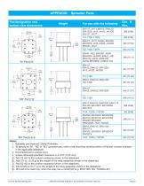
Pad designation and bottom view dimensionsFor use with the following: Dim. H Max. 1. Spreader pad material: Diallyl Phthalate. 2. To specify an “M”, “M2” or “M3” spreader pad, refer to the mounting variants portion of the part number example in the applicable datasheet. 4. Unless otherwise specified, tolerance is ± .010” (0.25 mm). 5/. Add 25 mQ to the contact resistance shown in the datasheet. 6/. Add .01 oz. (0.25 g) to the weight of the relay assembly shown in the datasheet. 7/. Add 50 mQ to the contact resistance shown in the datasheet. 8/. Add 0.025 oz (0.71 g) to the weight of the relay...
Open the catalog to page 5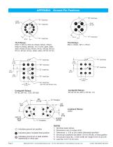
APPENDIX: Ground Pin Positions "Z" Centigrid® Relays: Centigrid® Relays: Indicates ground pin position Indicates glass insulated lead position Indicates ground pin or lead position depending on relay type Page 6 NOTES 1. Terminal views shown 2. Dimensions are in inches (mm) 3. Tolerances: ± .010 (±.25) unless otherwise specified 4. Ground pin positions are within .015 (0.38) dia. of true position 5. Ground pin head dia., 0.035 (0.89) ref: height 0.010 (0.25) ref. 6. Lead dia. 0.017 (0.43) nom.
Open the catalog to page 6All Teledyne Relays catalogs and technical brochures
 Space product selction guide
62 Pages
 Product overview
28 Pages
 732
7326 Pages
 722
7223 Pages
 H-33S
H-33S6 Pages
 Series HR412/ HRS412
10 Pages
 E3P Series
4 Pages
 LS10 Series
2 Pages
 Series EMCRT
4 Pages
 S3P series
2 Pages
 Series SQ
2 Pages
 Miniature Matrix
1 Page
 Matrix Selection Guide
28 Pages


Archived catalogs
 Series HR255/HR257
11 Pages
 Series H-32N
6 Pages
 172
1726 Pages
 122C
122C6 Pages


- Single-pole switch
- Switching relay
- Technology switch
- Multipole switch
- Electromechanical switch
- DC electromechanical relay
- Solid state relay
- Transfer switch
- Power relay
- Printed circuit board electromechanical relay
- DC solid state relay
- AC electromechanical relay
- 12VDC electromechanical relay
- Mechanical switch
- Bistable electromechanical relay
- Interlock electric switch
- Compact electromechanical relay
- Power solid state relay
- 3-pole electric switch