- Company
- Products
- Catalogs
- News & Trends
- Exhibitions
172
1 /6Pages

172
1 /6Pages
Catalog excerpts
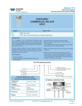
TELEDYNE RELAYS Everywhereyoulook" Series 172 DPDT Non-Latching Commercial Electromechanical Relay Sliljj DESCRIPTION The 172 Centigrid® relay is an ultraminiature, hermetically sealed, armature relay for commercial applications. Its low profile height (.280”) and .100” grid spaced terminals, which preclude the need for spreader pads, make it an ideal choice where extreme packaging density and/or close PC board spacing are required. The basic operating concept and internal structure are similar to Teledyne's DPDT 114 Centigrid® relay. Unique construction features and manufacturing techniques provide overall high reliability and excellent resistance to environmental extremes: The 172 feature: • All welded construction. • Unique uni-frame design providing high magnetic efficiency and mechanical rigidity. • High force/mass ratios for resistance to shock and vibration. • Advanced cleaning techniques provide maximum assurance of internal cleanliness. • Precious metal alloy contact material with gold plating assures excellent high current and dry circuit switching capabilities. The Series 172 relay has an internal discrete silicon diode for coil transient suppression. By virtue of its inherently low intercontact capacitance and contact circuit losses, the 172 relay is an excellent subminiature RF switch for frequencies well into the UHF spectrum (see Figure 1). Applications include telecommunications, test instruments, mobile communications, attenuators, and automatic test equipment. 172 Y M4 Relay Series Ground Pin Option i (See Appendix) Pad Option (See Appendix) 26 / S Q Q = Solder-Coated Leads1 G = Gold-Plated Leads (RoHS Compliant) R = RoHS Compliant Solder2 S = 0.187” Leads No Suffix = 0.75” Leads Nominal Coil Voltage (26 = 26.5 V, See Page 2 for more Voltages) © 2018 TELEDYNE RELAYS (800) 284-7007 • www.teledynerelays.com
Open the catalog to page 1
TELEDYNE RELAYS Everywhereyoulook' Series 172 DPDT Non-Latching Commercial Electromechanical RelaySERIES 172 GENERAL ELECTRICAL SPECIFICATIONS (@25°C) Contact Arrangement DETAILED ELECTRICAL SPECIFICATIONS (@25°C) GENERAL NOTES 1. Relay contacts will exhibit no chatter in excess of 10 psec or transfer in excess of 1 ^sec. 2. “Typical” characteristics are based on available data and are best estimates. No on-going verification tests are performed. 3. Unless otherwise specified, parameters are initial values. 4. Relays can be supplied with a spacer pad. See appendix. 172 Page 2 SPECIFICATIONS...
Open the catalog to page 2
DPDT Non-Latching Commercial Electromechanical Relay SERIES 172 OUTLINE DIMENSIONS .750 MIN. (19.05) DIMENSIONS ARE SHOWN IN INCHES (MILLIMETERS) (Viewed From Terminals) SCHEMATIC DIAGRAMS 7 NOTES: 1. RELAY CONTACTS WILL EXHIBIT NO CHATTER IN EXCESS OF 10 ΜSEC OR TRANSFER IN EXCESS OF 1 ΜSEC. 2. “TYPICAL” CHARACTERISTICS ARE BASED ON AVAILABLE DATA AND ARE BEST ESTIMATES. NO ON-GOING VERIFICATION TESTS ARE PERFORMED. 3. UNLESS OTHERWISE SPECIFIED, PARAMETERS ARE INITIAL VALUES. 4. RELAYS CAN BE SUPPLIED WITH A SPACER PAD. SEE APPENDIX.
Open the catalog to page 3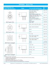
APPENDIX: Spacer Pads Pad designation and bottom view dimensions Notes: 1. Spacer pad material: Polyester film. 2. To specify an “M4” or “M9” spacer pad, refer to the mounting variants portion of the part numbering example in the applicable datasheet. 3. Dimensions are in inches (mm). 4. Unless otherwise specified, tolerance is ± .010” (.25 mm). 5. Add 10 mΩ to the contact resistance shown in the datasheet. 6. Add 0.01 oz. (0.25 g) to the weight of the relay assembly shown in the datasheet. Page 4
Open the catalog to page 4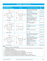
Pad designation and bottom view dimensionsFor use with the following: Dim. H Max. 1. Spreader pad material: Diallyl Phthalate. 2. To specify an “M”, “M2” or “M3” spreader pad, refer to the mounting variants portion of the part number example in the applicable datasheet. 4. Unless otherwise specified, tolerance is ± .010” (0.25 mm). 5/. Add 25 mQ to the contact resistance shown in the datasheet. 6/. Add .01 oz. (0.25 g) to the weight of the relay assembly shown in the datasheet. 7/. Add 50 mQ to the contact resistance shown in the datasheet. 8/. Add 0.025 oz (0.71 g) to the weight of the relay...
Open the catalog to page 5
APPENDIX: Ground Pin Positions "Z" Centigrid® Relays: Centigrid® Relays: Indicates ground pin position Indicates glass insulated lead position Indicates ground pin or lead position depending on relay type Page 6 NOTES 1. Terminal views shown 2. Dimensions are in inches (mm) 3. Tolerances: ± .010 (±.25) unless otherwise specified 4. Ground pin positions are within .015 (0.38) dia. of true position 5. Ground pin head dia., 0.035 (0.89) ref: height 0.010 (0.25) ref. 6. Lead dia. 0.017 (0.43) nom.
Open the catalog to page 6All Teledyne Relays catalogs and technical brochures
 Space product selction guide
62 Pages
 Product overview
28 Pages
 732
7326 Pages
 722
7223 Pages
 712
7126 Pages
 H-33S
H-33S6 Pages
 Series HR412/ HRS412
10 Pages
 E3P Series
4 Pages
 LS10 Series
2 Pages
 Series EMCRT
4 Pages
 S3P series
2 Pages
 Series SQ
2 Pages
 Miniature Matrix
1 Page
 Matrix Selection Guide
28 Pages


Archived catalogs
 Series HR255/HR257
11 Pages
 Series H-32N
6 Pages
 122C
122C6 Pages


- Single-pole switch
- Switching relay
- Technology switch
- Multipole switch
- Electromechanical switch
- DC electromechanical relay
- Solid state relay
- Transfer switch
- Power relay
- Printed circuit board electromechanical relay
- DC solid state relay
- AC electromechanical relay
- 12VDC electromechanical relay
- Mechanical switch
- Bistable electromechanical relay
- Interlock electric switch
- Compact electromechanical relay
- Power solid state relay
- 3-pole electric switch